 中文
 English

IRF7726TR P-Channel MOSFET Replacement: Pb-Free or New Device
 Back to previous page

The IRF7726TR is a single P-channel MOSFET in the Micro8 package, 3 by 3 mm and 0.91 mm tall, rated -30V with 26 milliohms at 10V gate drive and -7.0A at 25C ambient. It sits in the battery master switch of power tools and power banks, in the pack-to-system power path, in high-current load switches behind USB ports and motor branches, and in OR-ing between a battery and an adapter. Current in these positions runs from 4A to 6A, the gate is static, and the board still gives the power device only 1.2 mm of clearance.
The manufacturer lists this order code as Obsolete, and distributors flag it RoHS non-compliant. IRF7726TR carries no Pb-free suffix, its lead finish is tin-lead, and the tape holds 4000 pieces per reel.
The lead-free code, IRF7726TRPBF, is the same die and is still in production. It appears in the 2026 small-signal selection guide, ships on tape, and is rated MSL 1. That difference produces two routes on this path: change the part number to IRF7726TRPBF, or change the device to VBA8338. The first route touches no circuit and changes no electrical spec. The second cuts on-resistance by 31% and gate charge by 46%, but its board-level rating at 25C is only -6.0A. In a 7A path, that one number comes before every other parameter.
Where the part sits
| Position | How it is wired | What it has to do |
|---|---|---|
| Battery master switch, power path | Source to system, drain to pack, gate pulled to ground through a resistor | Conducts continuously, so drop goes into runtime and heat |
| High-current load switch (USB port, motor branch) | Source to load, gate pulled low by a control pin or driver | Survives plug-in surge, static drop feeds the load |
| Battery and adapter OR-ing | Two devices sharing a drain or back to back, gates cross-controlled | Thresholds must match, body diode must not conduct backwards |
| Rail disconnect at 4.5V and below | In series with the rail, gate on a logic level | Stays low resistance at low gate voltage |
What these positions share is a gate that does not switch at rate, which makes switching loss irrelevant. The decision rests on conduction drop and on the thermal path.
Heat matters more here than on the 26 milliohm part's smaller sibling. Micro8 has eight leads and no thermal pad, so the junction-to-ambient resistance is 70C/W and every watt leaves through the leads and the copper. At 7A continuous in a 25C ambient, 26 milliohms dissipates 1.27W and the junction reaches 114C. The same 7A in an 85C enclosure puts the junction at 174C, past the 150C limit. The -7.0A figure holds only at 25C ambient; the datasheet gives -5.7A at 70C.
The current this path can actually carry sits between 5A and 6A, depending on copper area and enclosure temperature. That premise comes first; the rest of the comparison follows from it.
Three part numbers, three material states
Three codes appear across BOMs, approved vendor lists and purchasing sheets for this one die. Their material states differ, and that is what separates this part from the 90 milliohm device in the same family.
| Code | What it contains | Status | Finish |
|---|---|---|---|
| IRF7726 | Base die name | Not an orderable part number | None |
| IRF7726TR | Base plus TR (tape and reel) | Obsolete | Tin-lead, RoHS non-compliant |
| IRF7726TRPBF | Base plus TR plus PBF (Pb-free) | In production | Lead-free, halogen-free |
| IRF7726TRPBFXTMA1 | PBF plus a five-character ordering code | In production | Lead-free, halogen-free |
The sibling IRF7606TR is a different situation: its lead-free version was also discontinued, so only the device swap remains. IRF7726 still has a lead-free version in production, which makes the first question here whether to change the device at all. The six-device comparison already sorts this family of 3 by 3 mm single P-channel parts by current class.
The XTMA1 tail is not a new part. It is an ordering code that packs RoHS status, package type, pieces per reel and revision into the part number. The die is identical to IRF7726TRPBF.
Mixed coatings on one board
A board that carries IRF7726TR at one power position and IRF7726TRPBF at another is the most common way this design fails a compliance review.
RoHS judges the finished product by its worst part. Lead above 0.1% by homogeneous material fails, and a tin-lead finish runs to tens of percent, which an X-ray fluorescence scan of one lead reads in seconds. One position left on a leaded code blocks the declaration for the whole assembly, no matter how clean the rest of the board is.
Three consequences follow, none of them electrical.
The BOM and the approved vendor list disagree. Purchasing quotes from the BOM and receiving checks against the list. When the two disagree, the same die becomes two part numbers, two quotation rounds and two inspection records. Obsolete stock prices move, so the two numbers rarely settle at the same price.
Mixing cannot be caught at the feeder. The two codes differ in the last characters of the marking. A wrong reel at the feeder produces no placement error, and functional test will not catch it.
Traceability ends at the leaded reel. Surplus stock is usually re-reeled, and the date code on the label does not always match the die inside. When a lot fails, there is no path back to the manufacturer.
The conclusion is simple: two finishes cannot coexist on one board. Keeping the leaded part means declaring the whole assembly as leaded, which does not pass, so the leaded code has to go. That is exactly what changing to IRF7726TRPBF does.
What surplus stock does at 7A
Obsolete codes come from three sources: manufacturer inventory, channel surplus and third-party re-reeling. They look the same in a bag.
Re-reeling. The standard package is 4000 pieces on a reel in a moisture barrier bag with desiccant. A third party that breaks and rebuilds reels can change quantity, label and date code, and the original packaging state behind an MSL 1 rating can no longer be confirmed. Reflowing such parts on a no-bake assumption produces delamination and popcorning.
Lead oxidation. A tin-lead finish grows an oxide layer in storage and wettability drops. First articles look fine; after a full reflow the failure mode is a higher rate of cold joints at random positions.
Refurbished parts. Sanding and re-marking is the common method. The die may be genuine, but it has been through removal and reprocessing, and the on-resistance distribution drifts.
At 7A the drift is amplified by the square: loss is I squared R, so 20% more resistance means 20% more loss and 20% more rise. An 89C rise becomes 107C, and the junction in a 25C ambient moves from 114C to 132C. On the 3.6A device in the same family, the same drift moves a 33C rise to 40C, which still has margin. The 7A path does not.
This is why surplus stock is a poor basis for volume production on this path. Changing one suffix costs less than screening incoming lots.
Two routes and what each changes
Keeping the part number: IRF7726TRPBF
Same die, same package, same pinout, same threshold, same on-resistance, same gate charge, same thermal resistance. No circuit or PCB change. The BOM entry changes from `IRF7726TR` to `IRF7726TRPBF`.
Two things follow, both on the line.
Reflow profile. Leaded solder peaks near 235C, lead-free near 260C. One lead-free part on the board puts the whole board on the lead-free profile. A line that has always run leaded curves has to change the profile with the part number.
Incoming inspection basis. After the switch, the XRF criterion changes from no lead check to lead below 1000 ppm, and the incoming report and the declaration of conformity have to be updated together.
This route changes no performance figure: 26 milliohms at 10V drive, 40 milliohms at 4.5V drive, -7.0A at 25C. Heat and drop stay where they were.
Changing the device: VBA8338
The footprint is the same 3 by 3 mm eight-pin land pattern and the pinout matches, so the PCB stays. Three items need to be rechecked.
Current rating. The board-level rating at 25C goes from -7.0A to -6.0A, and at 70C from -5.7A to -4.6A. Any path carrying more than 4A continuous has to be recalculated against the new rating.
Steady-state thermal resistance. The replacement datasheet lists 40C/W typical and 50C/W maximum for t of 10 seconds or less, while footnote c on the same page gives 95C/W as the steady-state limit, and the power derating table is derived from 50. For a continuously conducting path the steady-state figure applies, and against the original's single 70C/W number the replacement is 36% worse.
Surge and current limiting. Lower on-resistance raises the peak current when a capacitive load is plugged in. A USB port that relied on 26 milliohms for incidental limiting will see a larger surge and may trip its protection earlier.
Surge calculations, limiting thresholds and body diode direction for the four positions are worked through in the IRF7726TRPBF article on the same die, and those conclusions carry over unchanged. The difference here is the material state and the current rating.
Comparison with VBA8338
The full comparison, using datasheet values only:
| Parameter | IRF7726TR | VBA8338 | Change |
|---|---|---|---|
| Package | Micro8 (3x3 mm) | MSOP8 (3x3 mm) | Pin compatible |
| VDSS | -30V | -30V | Same |
| VGS limit | plus or minus 20V | plus or minus 20V | Same |
| VGS(th) | -1.0V to -2.5V | -1.7V max | Overlapping |
| RDS(on) at -10V | 26 milliohms max (-7.0A) | 18 milliohms max (-7.0A) | 31% lower |
| RDS(on) at -4.5V | 40 milliohms max | 25 milliohms max (-5.6A) | 37% lower |
| ID at TA 25C | -7.0A | -6.0A | One step lower |
| ID at TA 70C | -5.7A | -4.6A | One step lower |
| Qg typical / max at -10V | 46nC / 69nC | 25nC / 38nC | 46% lower typical |
| Ciss | 2204pF | 1600pF | 27% lower |
| RthJA (t of 10 s or less) | 70C/W | 40C/W typical, 50C/W max | Better |
| RthJA (steady state) | 70C/W | 95C/W (footnote c) | 36% worse |
| PD at TA 25C | 1.79W | 2.5W | Higher figure |
| Body diode IS at TA 25C | -1.8A | -2.1A | Slightly better |
| Finish and status | Tin-lead, Obsolete | Halogen-free, in production | None |
Gate charge has to be compared on one basis: typical 46nC against 25nC is a 46% reduction, maximum 69nC against 38nC is 45%. Both lead to the same conclusion, but a typical value cannot be set against the other part's maximum.
Rise above ambient, using each part's steady-state thermal resistance and a 150C junction limit:
| Continuous current | Original loss | Original rise (70C/W) | Replacement loss | Replacement rise (95C/W) |
|---|---|---|---|---|
| 3A | 0.234W | 16C | 0.162W | 15C |
| 4A | 0.416W | 29C | 0.288W | 27C |
| 5A | 0.650W | 46C | 0.450W | 43C |
| 6A | 0.936W | 66C | 0.648W | 62C |
Resistance falls by 30% and steady-state thermal resistance rises by 36%. The two offset each other, and the rise is flat within a degree or two across all four currents. What actually drops is loss: 0.29W at 6A and 0.13W at 4A.
At 85C ambient the allowable dissipation is 150 minus 85, divided by thermal resistance: 0.93W for the original, which is 5.98A, and 0.68W for the replacement, which is 6.16A before the -6.0A rating caps it. Both land near 6A, so the replacement holds no current advantage.
Choosing by continuous current
| Case | Decision | Reason |
|---|---|---|
| Above 6A continuous | Change the part number only | Replacement is rated -6.0A, below a 7A path |
| 5A to 6A continuous | Prefer the part number change | Replacement rise is 43C to 62C, tight in an 85C enclosure |
| Up to 4A continuous | Device swap works | Saves 0.13W to 0.29W, rise is flat |
| Compliance only, no circuit change | Change the part number only | Identical electricals, one suffix |
| Mostly 4.5V gate drive | Device swap pays more | 40 milliohms against 25 milliohms, 37% lower |
| 2.5V logic pin directly on the gate | Neither route works | No 2.5V data for the replacement, threshold mismatch |
| Bus above 24V | Check breakdown first | Both are -30V, 24V is 80% of that |
The 4.5V point deserves one sentence. Gate drive in 3.3V systems sits near 4.5V, where the original is 40 milliohms and the replacement 25, a 37% cut, larger than the 31% at 10V. Direct drive from a 2.5V logic pin is a different case: the threshold maxima are -2.5V and -1.7V, so a 2.5V gate leaves 0.5V to 0.8V of overdrive, both parts sit in the linear region, and the real resistance is far above the datasheet figure. That position needs a driver or stays as it is.
Checks before the change
What is the continuous current on this path? Above 6A only the part number change works; below 4A the device swap pays.
What is the maximum enclosure temperature? The -7.0A figure is a 25C number, -5.7A at 70C, and under 6A once the ambient reaches 85C.
What is the gate drive voltage? At 4.5V and above the replacement gains most; at 2.5V direct drive neither part applies.
Does the board carry any other leaded code? One is enough to fail RoHS, and changing this part does not solve it.
How much copper is available? Both figures assume a one-inch-square pad. Less copper raises thermal resistance, and the 85C line moves down.
Is the reflow profile lead-free? IRF7726TRPBF and the replacement both require a 260C peak.
Is there an N-channel part in the same footprint? The 3 by 3 mm eight-pin land pattern is identical for both polarities, and a wrong reel produces no placement error.
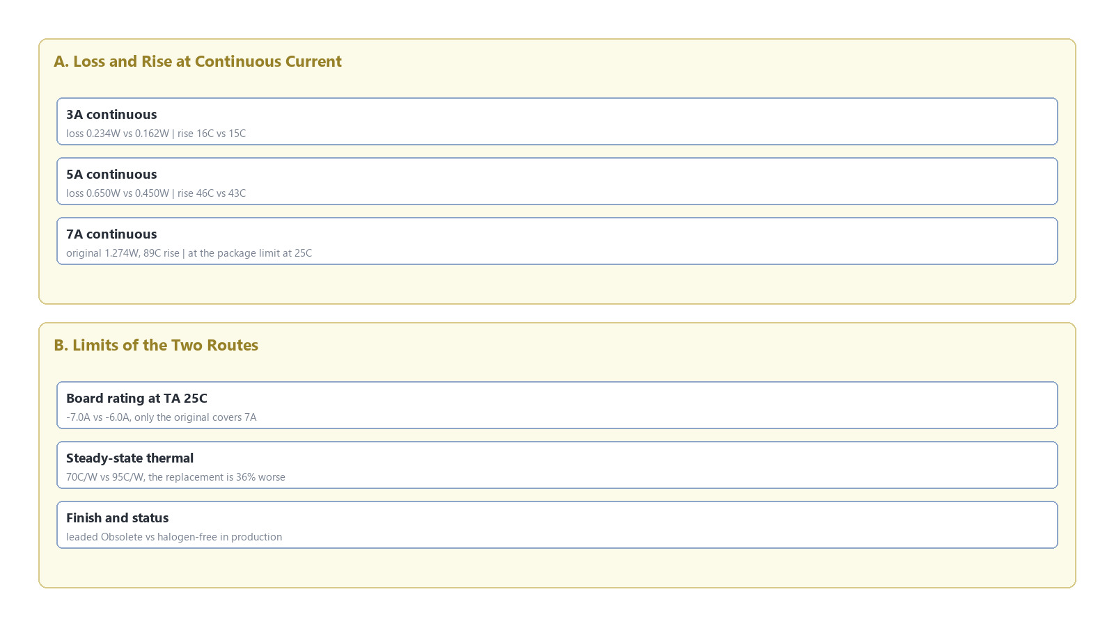
Figure 1: Loss and rise on the 7A path. On-resistance falls 31% while steady-state thermal resistance rises from 70C/W to 95C/W, so the rise is flat from 3A to 6A and the saving is in loss.
FAQ
Is the IRF7726TR discontinued? Yes. Distributors list it as Obsolete and RoHS non-compliant. The lead-free code, IRF7726TRPBF, is in production with identical electrical specifications.
If the lead-free version is still available, why change the device at all? The part number change fixes compliance and leaves performance at 26 milliohms and -7.0A. A device swap adds value only below 4A continuous, where lower loss or a second source matters. In a 7A path, the part number change is the only option that keeps the current rating.
Can a 7A position take VBA8338 directly? No. Its board-level rating is -6.0A at 25C and -4.6A at 70C, which is below a continuous 7A. At 85C ambient both parts land near 6A of usable current, so the replacement holds no advantage there.
Do IRF7726TR and IRF7726TRPBF differ electrically? No. Same die, and the only difference is the lead finish: tin-lead on the TR code, lead-free and halogen-free on the PBF code. Threshold, on-resistance, gate charge and thermal resistance are identical.
How much lower is the gate charge? On one basis: typical from 46nC to 25nC, a 46% reduction, and maximum from 69nC to 38nC, a 45% reduction. Setting the typical 25nC against the other part's maximum 69nC produces a wrong figure.
Can both codes be used on the same board? No. RoHS judges the finished product by its worst part, so one leaded position blocks the declaration. The two codes also share a footprint and differ only in the last marking characters, which no placement check will catch.

Download PDF document
 Download now


