 中文
 English

IRF7606TR P-Channel MOSFET Replacement: How TR and PBF Differ
 Back to previous page

The IRF7606TR is a single P-channel MOSFET in the Micro8 package: 3 by 3 millimetres, under 1.1 millimetres tall, -30V, -3.6A, 90 milliohms at 10V gate drive and 150 milliohms at 4.5V gate drive. It sits in battery disconnect circuits on handheld products, in ship-mode switches that cut the cell off when the device is powered down, in load switches for USB ports and peripheral rails, and in the handover between battery and adapter. Currents stay near 3 amps, the gate barely moves, and the board leaves about 1.2 millimetres of headroom for the part.
The manufacturer now lists the part as discontinued, mainstream distribution shows zero stock, and what remains is mostly inventory and reel tails. Separately, the plain `IRF7606TR` code has no PBF suffix, so its pin plating contains lead and fails RoHS. Projects that still carry that line on the BOM face two questions: which code is compliant, and whether to address thermal performance in the same change.
VBA8338 fits the same footprint: -30V, plus or minus 20V gate, 3 by 3 millimetre eight-pin, 18 milliohms at 10V drive. The three routes available differ in what they require, so they are covered separately.
Where the part sits
| Position | How it is wired | What the part must do |
|---|---|---|
| Battery master switch, ship mode | Source to system, drain to cell, gate pulled to ground through a resistor | Low leakage when off; low drop when on, because it is on continuously |
| Load switch, USB port or peripheral | Source to load, gate pulled low by the MCU or a divider | Survives inrush; static drop sets the load voltage |
| Battery to adapter handover | Two devices back to back or common drain, gates cross-controlled | Matched thresholds; no body-diode conduction in reverse |
| 3.3V and 5V rail isolation | In series with the rail, gate tied to a logic level | Still low resistance at low gate drive |
All four share one trait: the gate moves a few times a year at most, so switching loss is irrelevant and only on-resistance and heat decide whether the part works. The calculations below cover those two.
P-channel rather than N-channel, because there is no charge pump in a high-side position. An N-channel high-side switch needs its gate driven more than ten volts above the source, which requires a bootstrap capacitor or an isolated driver; a P-channel part turns on by pulling the gate to ground. On a handheld product that removes a driver IC and several passives. The trade is that a P-channel die is two to three times more resistive than an N-channel die of the same area, which has to be recovered with die area, so these parts are always the largest die that fits in 3 by 3 millimetres.
Micro8 rather than SO-8, because of height. Micro8 is 3 by 3 millimetres and under 1.1 millimetres tall; SO-8 is 5 by 4 millimetres and 1.75 millimetres. Many enclosures leave only 1.2 millimetres for power devices.
How the part number is built
Three spellings appear on BOMs, and purchasing often quotes them as three parts. There is one die behind all of them.
| Spelling | What it says | Status |
|---|---|---|
| IRF7606 | Base part name | Not an orderable number |
| IRF7606TR | Base plus TR, tape and reel | Legacy code, tin-lead pin plating; distributors list it obsolete and non-compliant |
| IRF7606TRPBF | Base plus TR plus PBF, lead-free | Same electricals as IRF7606TR; still documented, status discontinued |
`TR` describes packing, tape and reel. `PBF` describes plating, lead-free. The two suffixes describe different attributes, not different performance grades. PBF does not mark an improved revision; the die is unchanged and only the lead finish differs.
A longer form exists as well, for example IRF7726TRPBFXTMA1, with five extra characters. Those follow the orderable part number scheme, and each position carries meaning:
| Position | Meaning | Example |
|---|---|---|
| 1st | RoHS, halogen and total lead-free status | X |
| 2nd | Packing type and moisture-barrier packing | T means tape and reel, non-dry pack |
| 3rd | Units per reel band | M means 2001 to 5000 |
| 4th and 5th | Designator | A1 |
So IRF7726TRPBFXTMA1 and IRF7726TRPBF are the same device, with packing details folded into the number. The IRF7606 has not adopted this scheme; its orderable number remains IRF7606TRPBF, with packing listed separately as tape and reel, 4000 per reel, non-dry pack.
Why the leaded code fails compliance
RoHS limits lead to 0.1 percent by weight in any homogeneous material, which is 1000 parts per million. Pin plating is a homogeneous material, and tin-lead plating runs tens of percent lead. An X-ray fluorescence scan reads it in seconds.
Exemptions for lead do exist in electronics, but they cover cases such as high-melting-point solders and lead in glass or ceramic. Pin plating on a moulded package is not among them. From a design standpoint the leaded code has no available path.
Three points block it, and none is electrical.
Incoming inspection: most contract manufacturers own an XRF gun, and one scan on the leads produces a reading. A leaded lot is rejected the same day.
Customer audit: buyers ask for a RoHS declaration of conformity, a third-party test report, and a REACH SVHC statement. A leaded part fails the first document.
Export and line transfer: shipping into the EU requires a technical file, and moving a line requires resubmitting the bill of materials. Both reject the leaded code.
The manufacturer marks the IRF7606 as discontinued, DigiKey shows zero on hand, and remaining distribution stock is largely inventory and reel tails. Discontinued parts carry a premium and arrive in mixed lots, so propping up volume production on stock of unknown origin is a larger risk than changing one BOM line.
Changing to the lead-free code
This is the smallest change. IRF7606TRPBF and IRF7606TR share one die: same package, same pinout, same threshold, same on-resistance, same gate charge. Nothing on the schematic or the layout moves; the BOM line changes from `IRF7606TR` to `IRF7606TRPBF`.
Two items follow, both on the line rather than in the drawing.
Reflow profile: tin-lead solder peaks near 235 degrees Celsius, lead-free near 260. One lead-free device on the board means the whole board runs the lead-free profile. A legacy line still using a tin-lead profile has to change the profile along with the part number, or the lead-free parts wet poorly and the void rate rises.
Moisture sensitivity: the IRF7606 is rated at moisture sensitivity level 1 with non-dry packing, so no bake is required and there is no floor-life clock to track. That has to be reconfirmed when lots or channels change.
This route does not change performance. It is still 90 milliohms at 10V drive, 150 milliohms at 4.5V drive, -3.6A. If the board was already near its thermal or drop limit, the rename addresses compliance and leaves the heat where it was.
The thermal calculation for this die in a battery-switch position, and how each of the four positions should be judged, is worked through in the IRF7606TRPBF article, which covers performance. This article covers part numbers and compliance.
Comparison with VBA8338
The full comparison, using datasheet values only:
| Parameter | IRF7606TRPBF | VBA8338 | Change |
|---|---|---|---|
| Package | Micro8 (3x3mm) | MSOP8 (3x3mm) | Pin compatible |
| VDSS | -30V | -30V | Same |
| VGS max | plus or minus 20V | plus or minus 20V | Same |
| RDS(on) at -10V | 90 milliohms | 18 milliohms | Down 80 percent |
| RDS(on) at -4.5V | 150 milliohms | 25 milliohms | Down 83 percent |
| ID at TA 25C | -3.6A | -6.0A | One step up |
| Qg, typical | 20nC | 16nC | Slightly lower |
| Ciss | 520pF | 1600pF | Three times higher |
| RthJA, 10 seconds or less | 70 C/W | 40 typical, 50 max | Better |
| RthJA, steady state | 70 C/W | 95 C/W | 36 percent worse |
| Status | Discontinued | Active | — |
The larger difference is in the 4.5V drive column. The IRF7606TRPBF sits at 150 milliohms there, so 3 amps dissipates 1.35 watts, which against 70 C/W is a 94 degree rise. In a 70 degree ambient the junction crosses the 150 degree limit. On a 4.5V gate this device carries about 2 amps: 0.6 watts, a 42 degree rise.
Same 3 amps, same 4.5V gate, with the VBA8338: 25 milliohms, 0.225 watts, 21 degrees against the 95 C/W steady-state figure.
At 10V drive, 3 amps drops loss from 0.81 watts to 0.162 watts.
Gate drive and thermal checks
Gate drive strength: input capacitance goes from 520pF to 1600pF, so the driver sees a heavier load. Where an RC delay or a large pull-down sits ahead of the gate, turn-on stretches and soft-start timing needs recalculating. As a static switch the effect is limited; as a PWM switch the driver has to be able to push it.
Copper area: steady-state thermal resistance moves from 70 to 95 C/W, so the same loss produces a higher rise. In the 3 amp case above the replacement still runs cooler, because resistance fell far more than thermal resistance rose. As load drops toward 1 amp the resistance advantage narrows and the thermal penalty surfaces, so the original copper should not simply be carried over.
Land pattern and stencil: one package is called Micro8 and the other MSOP8, both 3 by 3 millimetre eight-pin with matching pin definitions. Stencil apertures and the reflow profile should be checked against the new datasheet rather than assumed from matching dimensions.
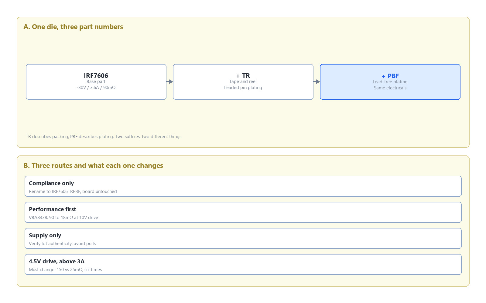
Figure 1: How the IRF7606TR part number is built, and what each of the three routes changes. TR indicates tape and reel packing, PBF indicates lead-free plating, and neither describes a performance grade.
Which route fits
| Situation | Route | What changes |
|---|---|---|
| BOM reads IRF7606TR, circuit fixed, compliance is the goal | Change the code to IRF7606TRPBF | One BOM line and the reflow profile |
| This position is at its thermal or drop limit, or runs a 4.5V gate | Switch to VBA8338 | Part number, drive check, copper |
| The part cannot be bought, no design change wanted | Verify lot and source | Avoid pulls and lots of unknown date code |
| 4.5V drive, above 3 amps | VBA8338, or change the drive circuit | A code change alone will not fix it |
Where the board already used the 90 milliohm part and discontinuation is only the trigger, confirm that the 3.6 amp class is still the right one. The 7A sibling IRF7726TRPBF is a different device with different resistance and current, which makes it a re-selection. A side-by-side of the six single P-channel parts in this class is collected separately.
Checklist
Which spelling is on the BOM. Only `IRF7606TR` is leaded. If it already reads `IRF7606TRPBF`, compliance is settled and only supply remains open.
Gate drive voltage. 10V drive gives the largest gain with the VBA8338; 4.5V drive calls for the change even more; 2.5V direct drive suits neither code, since both sit in the linear region.
Continuous current. Up to 3 amps either part passes. Above 3 amps on a 4.5V gate the original is already outside its rating.
Reflow profile. Any move to PBF or to the VBA8338 requires a lead-free process.
Copper area. Both datasheets quote thermal resistance on a one-inch square board, and less copper means higher resistance.
N-channel parts in the same package. A 3 by 3 eight-pin P-channel and N-channel share a land pattern, so placement will not flag the mix and the first power-up will.
FAQ
What is the difference between the IRF7606TR and the IRF7606TRPBF? Same die, different lead finish: TR is tin-lead, PBF is lead-free. Electricals match at -30V, -3.6A, 90 milliohms at 10V drive, 150 milliohms at 4.5V drive, and 20nC gate charge. The choice follows compliance requirements, not performance.
Can a board that lists IRF7606TR just change the part number? Yes. Package, pinout, threshold, on-resistance and gate charge all match, so the PCB stays as it is. The reflow profile has to change to lead-free, peaking near 260 degrees Celsius instead of about 235.
Is the IRF7606TRPBF discontinued, and can it be sourced long term? The manufacturer lists the part as discontinued, DigiKey shows zero stock, and remaining distribution stock is largely inventory and reel tails. Continuing with it means accepting mixed lots and a premium; long-term supply needs an active device.
Does the VBA8338 require a PCB change? Both are 3 by 3 millimetre eight-pin packages with matching pin definitions, so the board stays. Gate drive strength and copper area need review, since input capacitance goes from 520pF to 1600pF and steady-state thermal resistance from 70 to 95 C/W.
How far apart are the two parts on a 4.5V gate? The IRF7606TRPBF is 150 milliohms and the VBA8338 is 25. At 3 amps the losses are 1.35 and 0.225 watts, which against each part's own thermal resistance gives roughly 94 and 21 degrees of rise. The original suits about 2 amps on a 4.5V gate.
What are the five characters after the part number? They follow the orderable part number scheme, encoding RoHS and halogen status, packing type and moisture barrier, reel quantity band, and a designator such as XTMA1. TR indicates tape and reel packing and PBF indicates lead-free plating; the suffixes describe different attributes and point to the same die.

Download PDF document
 Download now


