 中文
 English

IRF7606TRPBF P-Channel MOSFET Battery Switch Selection: 5x Lower RDS(on)
 Back to previous page

IRF7606TRPBF is a single P-channel in Infineon's Micro8 package: 3 x 3 mm, under 1.1 mm tall, -30V, -3.6A, 90 mOhm. Where it appears is predictable. The cell that switches battery power in a handheld. The ship-mode switch that disconnects the pack completely once the system is off. The load switch behind a USB port or a peripheral rail. The 3V-to-5V transfer between a battery and an adapter. What these positions share is low current (around 3A), a gate that never moves, and almost no board height or footprint to spare. It reached end-of-life around 2020; what ships today is stock and tape-and-reel remainders.
The replacement is VBA8338: also -30V, also +/-20V gate, also a 3 x 3 mm eight-lead package, with 18 mOhm on-resistance. On the first page of the datasheet this looks like a fivefold upgrade. Spread the thermal conditions of both parts on the table and about a quarter of that fivefold gain has to be given back: its junction-to-ambient thermal resistance is 95 C/W against 70 C/W for the original. This article is about that gap, about which position can be swapped outright, which needs the current recomputed, and why the "-7A" headline figure is not reachable on a board.
At a glance
On-resistance drops from 90 mOhm to 18 mOhm; at 3A the drop falls from 0.27V to 0.054V. That part is real, and it is fivefold.
Thermal resistance rises from 70 C/W to 95 C/W. The substitute runs hotter per watt dissipated. A higher current rating does not mean copper can be skipped.
The current ratings are not comparable as printed. The original's -3.6A is a board-level figure at 25C ambient; the -7.0A on the substitute's front page is at 25C case temperature. Board-level it is -6.0A.
Folded to an 85C ambient, the original carries 3.2A and the substitute 6.0A. That gap is wider than the 1.67x on the labels, because the resistance falls further than the thermal resistance rises.
Input capacitance goes from 520pF to 1600pF and gate charge from 20nC to 25nC. Irrelevant for a static switch, decisive for a PWM switch.
Where it sits in the circuit
The position has to come first, because the same part number in different positions gives different answers. This device appears in four places, almost exclusively.
| Position | How it is connected | What the device must do |
|---|---|---|
| Battery master switch / ship mode | Source toward the system, drain toward the pack, gate pulled to ground through a resistor | Low leakage when off; low drop when on, because it is on for the life of the product |
| Load switch (USB port, peripherals) | Source toward the load, gate pulled low by an MCU through a divider or driver | Survive the inrush at turn-on; keep the static drop off the load |
| Battery-to-adapter transfer | Two devices back-to-back or common-drain, gates cross-controlled | Thresholds must match; neither body diode may conduct in reverse |
| 3.3V / 5V rail isolation | In series with the rail, gate tied to a logic level | Still low resistance at 4.5V or even 2.5V gate drive |
All four share one property: the gate moves a few times a year. Switching loss is irrelevant here. Only two things decide whether the part works: conduction drop and heat. That is why every calculation below is about resistance and thermal resistance, and none of it is about switching speed.
Why a small P-channel, and why this small
It is P-channel rather than N-channel because there is no charge pump at a high-side position. An N-channel on the high side needs its gate a dozen volts above the source to be fully on, which means a bootstrap capacitor or an isolated driver. A P-channel opens by pulling its gate to ground. In a handheld, deleting that driver path deletes a chip, a handful of capacitors and a layout problem. The price is that a P-channel is inherently two to three times more resistive than an N-channel of the same area, which is why the P-channels in this position are pushed to the 3 x 3 mm limit rather than something smaller.
It is not an SO-8 because of height. Micro8 and MSOP8 are both 3 x 3 mm and under 1.1 mm tall; SO-8 is 5 x 4 mm and 1.75 mm. Phones, earbud cases and handheld instruments routinely leave 1.2 mm of clearance for power devices. An SO-8 hits the enclosure. So a replacement here must match the package exactly; an SO-8 is not a workable compromise.
After the swap to VBA8338
The full comparison, datasheet figures only:
| Parameter | IRF7606TRPBF | VBA8338 | Change |
|---|---|---|---|
| Package | Micro8 (3x3 mm) | MSOP8 (3x3 mm) | Footprint compatible |
| VDSS | -30V | -30V | Same |
| VGS rating | +/-20V | +/-20V | Same |
| RDS(on) at -10V | 90 mOhm | 18 mOhm | One fifth |
| RDS(on) at -4.5V | 150 mOhm | 25 mOhm | One sixth |
| ID at TA=25C | -3.6A | -6.0A | 1.67x |
| ID at TC=25C | not stated | -7.0A | Case temperature, not reachable on a board |
| VGS(th) | -1.0V (min) | -1.7V | Deeper; recheck low-voltage drive |
| Qg at -10V | 20nC | 25nC | 25% more |
| Ciss | 520pF | 1600pF | 3x |
| RthJA (steady state) | 70 C/W | 95 C/W | 36% worse |
| Pd at TA=25C | 1.8W | 2.5W | Figure improves, thermal resistance does not |
| Status | Discontinued | Active |
The last four rows are where the entire risk of this swap lives. The first three are the comfortable part.
The gain is conduction drop. At 3A the original drops 0.27V and the substitute 0.054V. On a 3.7V pack feeding a 3A load, that 0.216V means 0.65W that no longer becomes heat: roughly 93% efficiency at that stage for the original against 98.6% for the substitute. For a product sold on battery life, that is not a rounding error.
The cost is thermal resistance. 95 against 70 means 36% more temperature rise per watt. Fortunately the losses are small to begin with: at 3A the substitute burns 0.16W and rises 15C, while the original burns 0.81W and rises 57C. The net is still a win, just not a fivefold one. Measured by temperature rise the improvement is 3.7x, not 5x, and certainly not the 1.67x the current labels suggest.
The row most often skipped is Pd. The substitute lists 2.5W against 1.8W, which reads as better heat handling. But Pd is derived from thermal resistance and a 150C junction limit; it does not mean the part sheds heat better. What actually sets usable current is (150 minus ambient) divided by thermal resistance, and the substitute has the larger denominator.
Worked out with a 150C junction limit:
| Ambient | Usable current, original | Usable current, substitute | Basis |
|---|---|---|---|
| 25C | 3.6A | 6.0A | Both hit the package rating |
| 55C | 3.6A | 6.0A | Same |
| 85C | 3.2A | 6.0A | Original pushed down to 3.2A; substitute still at the 6A rating |
The hotter it gets, the faster the original's margin disappears, while the substitute stays pinned at its package rating because its resistance is low. That is the real gap: 1.67x at 25C, close to 1.9x at 85C. Inverted, if your load is 2A, the original still has 1.2A of margin at 85C. Swapping changes battery life, not reliability.
The four positions, judged separately
Battery master switch / ship mode: swap directly. It is on continuously and barely switches, so larger Qg and Ciss cost nothing. One detail to check is the gate pull-down resistor: the substitute's -1.7V threshold is deeper than the original's -1.0V, so it turns off more decisively with the same resistor. No change needed. Inrush at power-up is limited by soft-start or pack impedance, and both parts handle the -20A pulse.
Load switch (USB port, peripherals): swap directly, but check inrush. Lower on-resistance means a higher peak when a capacitive load is plugged in, since peak current is pack voltage divided by on-resistance plus loop resistance plus capacitor ESR. If the original's 90 mOhm was doing incidental current limiting, the substitute removes that. Either add soft-start or put a small resistor at the source.
Battery-to-adapter transfer: recheck threshold matching. Back-to-back or common-drain structures rely on thresholds and body-diode direction working together. A deeper threshold moves the handover point, so confirm both devices still conduct reliably at the lowest pack voltage, say 3.0V. Do not swap this position without reading the circuit.
3.3V / 5V rail isolation: recompute the drive. At 4.5V gate drive the substitute is 25 mOhm, which is fine. With the gate tied directly to a 2.5V or 2.7V logic pin, overdrive is only 0.8V to 1.0V and the part sits in the linear region with far higher effective resistance than specified. The original is also poor there at 90 mOhm, but its shallower threshold leaves it slightly better off. Either add a driver stage or leave this one alone.
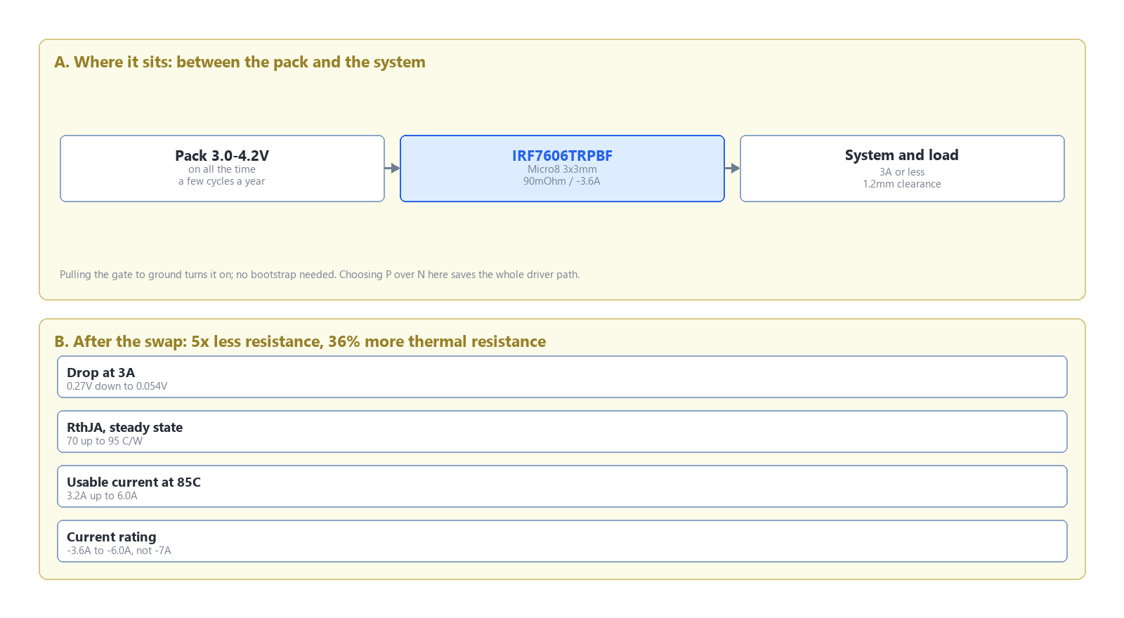
Figure 1. IRF7606TRPBF sits between the pack and the system. The VBA8338 drops the conduction loss fivefold, but junction-to-ambient thermal resistance rises from 70 C/W to 95 C/W, widening the usable-current gap at 85C from 1.67x to about 1.9x.
Five things to check before the swap
What the gate drive voltage is. At 4.5V and above the substitute's 25 mOhm is safe. At 2.5V to 3.0V direct drive, both parts are in the linear region; do not swap.
How much copper the board gives. The 95 C/W figure assumes a 1-inch-square, 2-ounce test board. Less copper means a higher number, and the 85C row has to move down.
Peak current and duration. Steady-state current follows the table above; pulse current is a safe-operating-area question, not this curve. Inrush into a capacitive load needs its own check.
Whether the gate has a clamp or divider. Both parts are +/-20V, so any rail up to 12V is safe. On a 24V rail the gate loop needs a clamp either way.
Whether the BOM also carries an N-channel in the same package. A 3 x 3 mm eight-lead P-channel and N-channel share a footprint. The pick-and-place will not complain; the first power-up will.
When not to swap
Continuous current above 6A. That is the thermal ceiling of a 3 x 3 mm package, and 18 mOhm does not change the package. More current means a thermal-pad SO-8 or DFN, not another part in this footprint.
A rail above 30V. Both are -30V parts; at 80% derating that is a 24V rail. Beyond that you need a different voltage class, and the package changes with it.
PWM dimming or synchronous rectification. Ciss going from 520pF to 1600pF and Qg from 20nC to 25nC triples the drive loss here. IRF7606TRPBF was never a switching-supply device, but if your circuit really does switch it at tens of kHz, the driver will run noticeably hotter after the swap.
2.5V logic drive with no driver stage. Said above, repeated here: this is the one case where every electrical parameter appears to pass and the swap still fails in the field.
The other side of a complementary pair, and the gate-rating question at a supply inlet, are written up in this note on inlet gate voltage; the side-by-side of four common positions is in this high-side position note.
FAQ
Is IRF7606TRPBF discontinued, and can genuine parts still be bought. Yes to both, but what remains is stock and tail-end reel, with no batch consistency. The risk is not the first order; it is the reorder two years out, which may bring refurbished or relabelled parts.
Is VBA8338 a 7A part or a 6A part. The front page says -7.0A, which is at 25C case temperature and assumes near-infinite heatsinking. On a board, by ambient temperature, it is -6.0A at 25C and -4.6A at 70C. Select with the latter set.
Does the circuit need changes after the swap. Three of the four positions need none. The 2.5V direct-drive case and the battery-to-adapter transfer do.
Why is the thermal resistance worse on the lower-resistance part. How much heat a 3 x 3 mm package sheds is set mostly by leads and pad area, and the two vendors' thermal paths differ. The substitute has a larger die, which buys the lower resistance, but its package path did not improve proportionally, so RthJA rises.
Can it be used on a 24V system. Yes, 80% of -30V is 24V, exactly at the boundary. With transient spikes on the rail, leave more margin or add a TVS.

Download PDF document
 Download now


