 中文
 English

IRF7506TRPBF Dual P-Channel MOSFET Power Path Selection: High-Side Use
 Back to previous page

IRF7506TRPBF is the orderable code for the IRF7506: -30V, dual P-channel, eight-pad Micro8, 4000 per reel. It has one job in a circuit, and it is always the same job — source tied to a rail, gate pulled low to turn on. So a replacement study cannot start at the first row of the datasheet. It starts with where the part sits, then asks what the substitute looks like in that same spot. This note is organised by position; only the parameters that matter at each position get discussed.
At a glance
It is a high-side switch: load switching, battery reverse protection, supply OR-ing. P-channel is chosen so the gate needs no bootstrap.
Dual P means two independent dice in one package, taking half the footprint of an SO-8.
The direct substitute is VBA9338, same package, same -30V class, 270 mOhm down to 38 mOhm at 10V.
Heat is the second ceiling: the package goes from 0.65W to 0.76W of allowed dissipation, a 17% gain, nothing like the 7x gain in resistance.
Three positions should not be swapped at all: low current at high frequency, a rail already close to 30V, and a drawing that names the original part.
Where the part actually sits
A P-channel device exists at this power level for exactly one reason: with the source on the rail, pulling the gate to ground turns it on, and no bootstrap or charge pump is needed. An N-channel high-side switch needs a gate drive above the rail, which rarely pays on a small board. Every typical position follows from that:
| Position | Connection | What it forces on the device |
|---|---|---|
| High-side load switch | Source on the rail, gate pulled down through a resistor or small NPN | Low on-resistance; the drop eats directly into load headroom |
| Battery reverse protection | One P in series with the battery positive, gate to the return side | Blocks when reverse-biased; conduction loss sets the heat |
| Supply OR-ing | One P per source, adapter and battery | Both channels matched, low reverse leakage |
| Small DC-DC high side | Synchronous buck upper switch | This one trades switching loss; gate charge outranks resistance |
The first three positions care about conduction. The fourth cares about switching. The same part can give opposite answers at the two ends, and that is where replacement studies go wrong.
Why dual
Two independent dice share one Micro8, with D1 and D2 brought out separately on pins 7-8 and 5-6. The usual arrangement is one channel for the battery path and one for a load switch. The package is half an SO-8 and under 1.1 mm tall, which is why it ended up in portable equipment and PCMCIA cards.
For a swap, "dual" means two things: the two dice have to be checked separately, and the pinout has to line up one for one. Eight-pad dual P-channel parts come in common-drain and independent variants, same package, different internal wiring.
What changes with VBA9338
Same package, same -30V, same +/-20V gate. The difference is in conduction and charge:
| Parameter | IRF7506TRPBF | VBA9338 | At 10V drive |
|---|---|---|---|
| RDS(on) at 10V | 270 mOhm | 38 mOhm | 7.1x lower |
| RDS(on) at 4.5V | 450 mOhm | 55 mOhm | 8.2x lower |
| Continuous current | -1.7A | -6A | 3.5x the rating |
| Qg at 10V | 7.5 nC | 50 nC | 6.7x higher |
| RthJA steady state | 100 K/W | 85 K/W | 17% better |
The first three rows are the gain, the fourth is the price, and the fifth is the row everyone skips: the package only gets 17% better at getting rid of heat. At 150C junction and 85C ambient, the original allows 0.65W and the substitute 0.76W. Converted to current at 10V drive that is 1.55A against 4.47A — 2.9x, which reads well until you notice how far it is from the -6A headline. At high current the real ceiling is how much heat an eight-pad package can shed, not the first row of the datasheet.
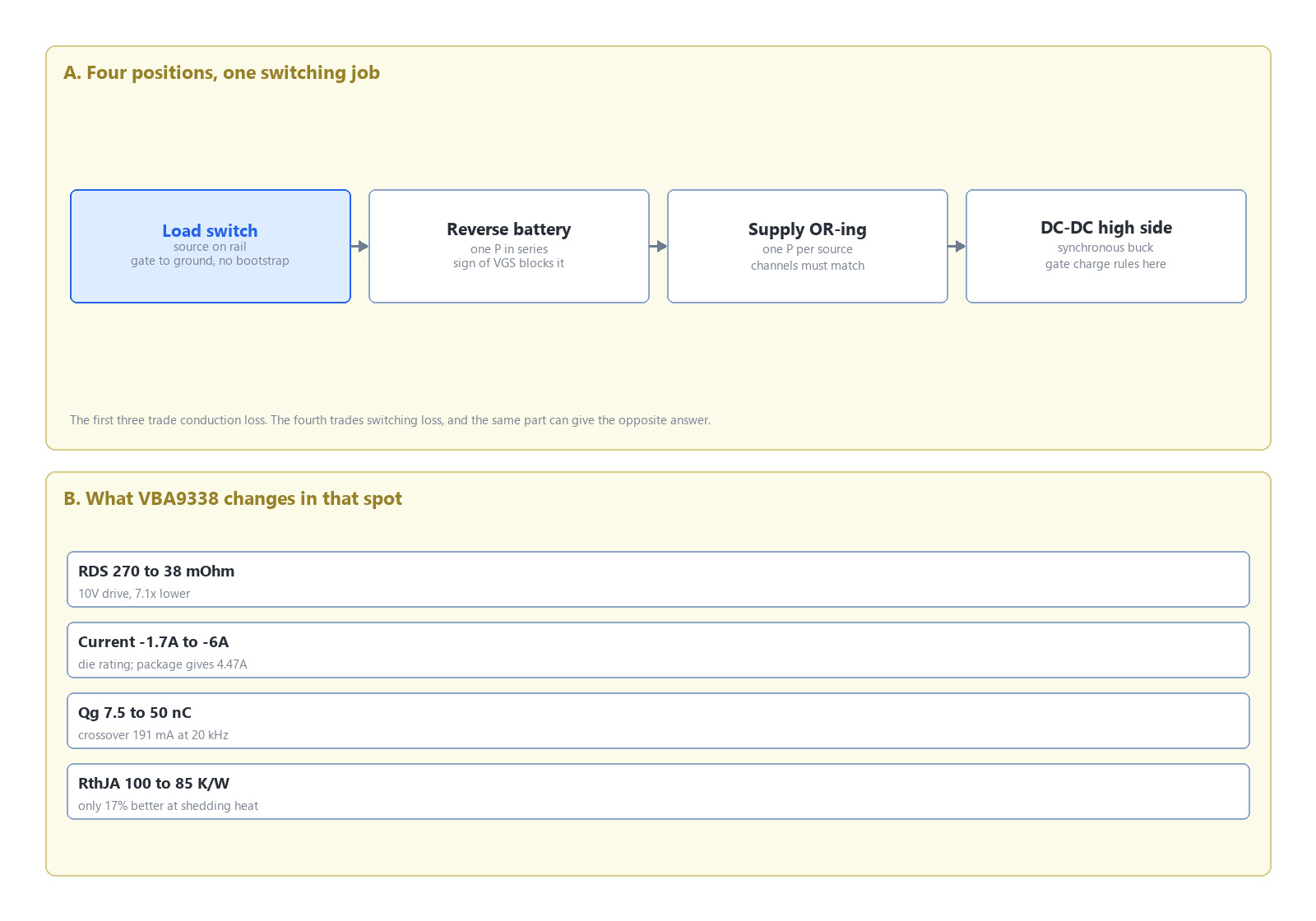
Figure 1. One part across four positions: the first three trade on conduction, the fourth on switching. Right panel: where each of the five parameters goes after the VBA9338 swap.
The four positions, judged separately
High-side load switch — swap directly. Below 1.5A with on/off duty rather than continuous switching, gate charge is irrelevant, and 7x less resistance takes the drop and the temperature rise down together.
Battery reverse protection — swap directly, but re-check the gate loop. Reverse protection works off the sign of VGS, so the substitute's threshold has to land in the same window; the original is -1.0V to -3.0V.
Dual-supply OR-ing — swap directly, but swap both. The two devices in an OR-ing pair need matching characteristics; change only one and the drop and reverse leakage of the two paths diverge, so at handover current back-feeds from the new part into the old one.
Small DC-DC high side — recompute. Qg goes from 7.5 nC to 50 nC, and the crossover at 20 kHz sits at 191 mA; below that load the swap loses more than it saves. The arithmetic is in the IRF7506 note. For the same trade in the 20V class, the IRF7504 note works it through.
Six things to check before the swap
Pinout and internal structure. Put the substitute's pin assignment next to the original, pin by pin, before the first prototype.
Consistency between the two dice. Dual parts need both channels checked, not one typical value.
Threshold window. The original is -1.0V to -3.0V. On a 3.3V or 5V rail that window decides whether the part turns on fully.
Thermal resistance and steady-state dissipation. The 17% above; do not extrapolate current capability from the 7x resistance gain.
MSL and halogen. The original is MSL 1 with halogen-free marked no. A product claiming halogen-free could not use the original either, so the swap is the cheapest moment to fix it.
Reel quantity and change notification. 4000 per reel; a different count means a feeder setup change, and any change should arrive in writing before shipment.
Three cases where you should not swap
Current below the crossover, at high switching frequency. Gate charge outweighs resistance and the board burns more.
The rail already sits near 30V. Both parts are -30V, so the swap buys no headroom. On a 24V battery rail this part has 6V left; what needs changing is the voltage class, not the part number.
The customer drawing or the AVL names the original. That is a scheduling problem: a drawing revision with customer sign-off, or a fresh AVL qualification, both need prototypes alongside. The eight-pad outline these parts share does not change — only the paperwork does.
FAQ
Can two single P-channel parts replace one dual?
Yes, usually at worse area and cost. The value of a dual is two channels side by side, one placement pass, half an SO-8.
Is -6A a current this package can actually pass?
No. That is the die capability. In an 85C ambient the eight-pad package works out to roughly 4.47A at 10V drive. Size from the calculated number, not the rated one.
Does a swap need a fresh qualification?
Follow your own process; at minimum a temperature cycling and high-temperature reverse bias run. The original's twenty-one years of field history cannot be inherited, and what stands in for it is a bounded first lot.

Download PDF document
 Download now


