 中文
 English

ZXM64P02XTA P-Channel MOSFET Replacement: The 2.7V Gate Limit
 Back to previous page

The ZXM64P02XTA is a single P-channel MOSFET in MSOP8, 3 by 3 millimetres and eight pins, rated -20V, 90 mOhm maximum at 4.5V of gate drive and -3.5A continuous at 25C ambient. It turns up inside 12V rails: the disconnect switch behind a 12V adapter input, the load path of a single-cell pack, the power gating on a board with both 5V and 12V outputs, the low-side switch of a small motor or relay. The bus voltage in these places is not high. What decides whether the part works is whether the 2.7V to 3.3V of logic level at its gate is enough to open it.
The manufacturer lists the part as obsolete, and the last revision of the datasheet is Issue 2 from February 2008. The only member of the family still passing through distribution is the ZXM64P02XTC, which differs in reel size alone: 13-inch reel, 4000 units, identical electrical ratings.
For substitution, VBA8338 is the same package, the same pinout and a higher voltage class: -30V, 25 mOhm typical at 4.5V of drive, -6.0A continuous at a 25C ambient. Its on-resistance is roughly a quarter of the original and its thermal resistance is lower. The place this substitution goes wrong is not resistance or thermal resistance. It is the threshold: the original is a low-threshold part that opens at 2.7V of drive, and the replacement sits about a volt higher, so the same 2.7V opens it less.
Where the part sits
| Position | How it is connected | Why the -20V class |
|---|---|---|
| Disconnect switch behind a 12V adapter | Source faces the system, gate driven by a detect pin or an MCU | 12V plus inductive flyback, 20V is the usual ceiling |
| Load path of a single-cell pack | In series with the positive terminal, gate pulled low to conduct | 4.2V at full charge, reverse and surge stay under 12V |
| Power gating for 5V and 12V outputs | Two devices, one per rail, gates driven by the same logic | The 12V rail sets the voltage class |
| Low-side switch of a motor or relay | Gate driven straight from a logic pin, no pull-up | The supply is usually 5V or 12V |
All four positions share three properties: a logic-level gate, 1A to 2A of current, and long conduction time. The order of requirements in these positions is: it has to open first, then loss, then voltage margin.
Which column each number sits in
The specification table of this part splits into minimum, typical and maximum columns, and the key numbers are easy to misread. Checked against the coordinates of the printed table, they fall like this:
| Parameter | Value | Column | Condition |
|---|---|---|---|
| On-resistance | 0.090 Ohm | Maximum | 4.5V drive, -2.4A |
| On-resistance | 0.13 Ohm | Maximum | 2.7V drive, -1.2A |
| Gate threshold | -0.7V | Minimum | -250 uA, drain tied to source |
| Total gate charge | 6.9 nC | Maximum | -16V drain-source, 4.5V drive |
| Input capacitance | 900 pF | Typical | -15V drain-source, 1 MHz |
Resistance is printed as a maximum; threshold is printed as a minimum. The two directions matter. A minimum threshold means no part in the batch sits further from zero than -0.7V, so opening it takes no more than 0.7V of gate drive. That is not the same statement as "0.7V maximum", but the conclusion is the same: this is a part designed for low gate voltage, which is what the feature list means by low threshold and low gate drive.
The 90 mOhm maximum is not the same basis as the 25 mOhm typical that gets quoted for the same package elsewhere. Comparing a maximum against a typical inflates the ratio, and the comparison table below flags it separately.
Threshold and gate drive
At 2.7V of drive the datasheet gives 0.13 Ohm maximum, 44 percent above the 0.090 Ohm it gives at 4.5V. That number is measured, so the part does open at 2.7V. It simply does not open all the way.
The threshold is what decides whether a substitution holds. The ZXM64P02XTA sits at -0.7V in the minimum column. VBA8338 sits at -1.7V in the typical column. One volt apart, applied to a 2.7V gate:
| Gate drive | Overdrive on the original | Overdrive on the replacement | Datasheet resistance at that drive |
|---|---|---|---|
| 2.7V | 2.0V | 1.0V | Original yes, replacement no |
| 3.3V | 2.6V | 1.6V | Neither |
| 4.5V | 3.8V | 2.8V | Both |
| 10V | 9.3V | 8.3V | Both |
Overdrive is the drive voltage minus the magnitude of the threshold. At 2.7V the replacement is left with 1.0V of overdrive, and its specification table only covers 4.5V and 10V of drive. No data does not mean unusable, but it does mean the substitution cannot be treated as a drop-in. Either the drive gets raised to 4.5V or more, or the conduction drop and temperature rise get measured on the board, or the original stays.
This is the argument of this piece. Earlier parts in the series dealt with rating basis and thermal resistance: the NTTS2P03R2 article covers four rating sets and how the conditions behind the numbers decide which one applies. This part is different. On the electrical table it wins almost every row, and the one row it loses is the threshold.
Steady-state current at 85C
The -3.5A rating carries note (b), a 25C ambient and a time under 10 seconds. Continuous conduction moves to note (a), 113C/W, which means a 25 by 25 millimetre pad of single-sided 1-ounce copper in still air.
On that 113C/W, with a 150C junction limit and an 85C enclosure:
| Continuous current | Loss from 25C resistance | Loss with temperature rise | Junction | Verdict |
|---|---|---|---|---|
| 2.5A | 0.56W | 0.83W | 179C | Over the limit |
| 2.1A | 0.40W | 0.58W | 150C | At the limit |
| 1.5A | 0.20W | 0.30W | 119C | Usable |
On-resistance rises to 1.47 times its 25C value at a 150C junction, which takes 0.090 Ohm to 0.132 Ohm. Working from the 25C number alone gives 2.5A; putting the temperature coefficient back gives 2.1A, a difference of about twenty percent.
On the same board in the same 85C enclosure, the replacement's 95C/W steady-state thermal resistance would allow more than 4A, but the rating caps it first: the datasheet gives -6.0A at 25C ambient and -4.6A at 70C, which puts 85C near 4.0A. The original delivers 2.1A and the replacement 4.0A, and most of that gap comes from on-resistance rather than thermal resistance.
Parameter comparison with VBA8338
The full comparison of the two parts, using datasheet values only:
| Parameter | ZXM64P02XTA | VBA8338 | Note |
|---|---|---|---|
| Drain-source voltage | -20V | -30V | |
| Gate-source limit | +/-12V | +/-20V | |
| On-resistance at 4.5V | 0.090 Ohm max | 0.025 Ohm typ | Different columns, do not divide |
| On-resistance at 2.7V | 0.13 Ohm max | Not given | |
| On-resistance at 10V | Not given | 0.018 Ohm typ | |
| Gate threshold | -0.7V min | -1.7V typ | Different columns |
| Gate charge at 4.5V | 6.9 nC max | 20 nC max | Same column, comparable |
| Input capacitance at -15V | 900 pF typ | 1600 pF typ | Same bias, comparable |
| Steady-state thermal resistance | 113C/W | 95C/W | |
| Ten-second thermal resistance | 70C/W | 40C/W typ, 50C/W max | |
| Current rating at 25C ambient | -3.5A, ten-second basis | -6.0A, steady state | Different time conditions |
| Power rating at 25C ambient | 1.1W steady state | 2.5W | |
| Body diode continuous current | -2.0A | -2.1A | |
| Junction limit | 150C | 150C |
Four rows compare directly: voltage class, gate limit, input capacitance and junction limit, because the test conditions on both sides match. On-resistance and threshold sit in different columns, so they support an order of magnitude, not a precise factor. The current rating is a ten-second figure on the original and a steady-state figure on the replacement, and the real steady-state gap is wider than the printed numbers suggest.
Gate charge and switching loss
Drive loss is gate charge times drive voltage times frequency. The replacement's 20 nC is a maximum and the original's 6.9 nC is also a maximum, so the two compare directly: a factor of 2.9.
| Switching frequency | Drive loss, original at 12V | Drive loss, replacement at 12V | Against conduction loss at 2.1A |
|---|---|---|---|
| 50 kHz | 4.1 mW | 12 mW | Negligible |
| 100 kHz | 8.3 mW | 24 mW | Negligible |
| 500 kHz | 41 mW | 120 mW | Starting to matter |
Conduction loss at 2.1A is around 0.58W, and the replacement's 25 mOhm brings that under 0.15W. Drive loss does not register at that scale, so nothing needs recalculating below 500 kHz. Only above 500 kHz, with the current also dropping under 0.5A, do the two losses reach the same order.
Input capacitance goes from 900 pF to 1600 pF, up 78 percent. Both are measured at -15V drain-source, so the ratio carries over directly. It affects peak drive current and switching edge rate; it does not enter the loss equations on its own.
Three options and their conditions
| Option | Condition | Cost |
|---|---|---|
| Keep the ZXM64P02XTA or the ZXM64P02XTC | Gate drive at 3.3V or below, continuous current under 2A, stock still available | Obsolete part, supply is not durable |
| Replace with VBA8338 | Gate drive at 4.5V or above, more current or lower conduction loss needed | Drive loss rises, low gate voltage no longer works |
| Raise the drive, then replace | Logic pin is 2.7V or 3.3V but a higher rail exists on the board | Resistor divider or level shifting, board change |
The first option is the common one in repair and spares. The second suits new designs or boards that already drive at 4.5V or more. The third only makes sense when the design genuinely needs more current and the drive is what blocks it, and it carries the largest change.
Checks before substitution
| Check | How to verify | If it fails |
|---|---|---|
| Gate drive voltage | Measure gate to source, not the MCU supply | Below 4.5V, the replacement is not guaranteed to open fully |
| Gate resistor | Usually 10 to 100 Ohms; the replacement's charge is larger and the edge slower | Insufficient dead time allows shoot-through |
| Copper area | 95C/W assumes a 25 by 25 millimetre pad of 1-ounce copper | Less copper degrades thermal resistance proportionally |
| Body diode current | Freewheel current stays under -2.1A | Junction runs over the limit during freewheel |
| Package and pinout | MSOP8, pins 1 to 3 source, 4 gate, 5 to 8 drain | A different pinout cannot be soldered in place |
The pinout is identical on both parts, pins 1 to 3 source, 4 gate and 5 to 8 drain, so the package drops straight in. The gate drive row is the one that needs real work; the other four are a routine recheck of the existing design.
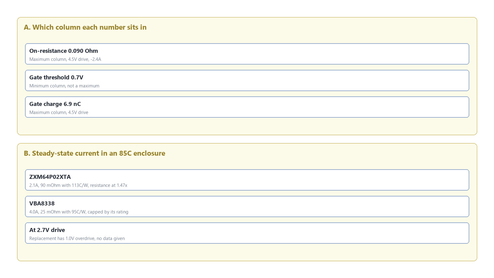
Figure 1. The column each key number sits in on the ZXM64P02XTA datasheet, and the steady-state current both parts can carry in an 85C enclosure. On-resistance of 0.090 Ohm and gate charge of 6.9 nC are maximums, while the 0.7V threshold is a minimum; 113C/W with 90 mOhm leaves 2.1A, and the replacement's 95C/W with 25 mOhm is capped by its current rating at about 4.0A.
FAQ
Is the 90 mOhm on the ZXM64P02XTA a typical or a maximum?
A maximum, at 4.5V drive and -2.4A. The other row, 0.13 Ohm, is also a maximum, at 2.7V drive and -1.2A. The datasheet gives no typical value.
Does moving from a -20V part to a -30V part cause any voltage problem?
No. A higher voltage class only adds margin. What needs rechecking is threshold, gate charge and package thermal resistance, since those are what change behaviour after substitution.
Can the VBA8338 be used at 2.7V of gate drive?
The datasheet gives no on-resistance at 2.7V, and the threshold typical is -1.7V, which leaves 1.0V of overdrive. That case cannot be treated as a direct substitution; either the drive goes to 4.5V or more, or it gets measured on the board.
Does the gate resistor need to change?
Normally not. The replacement's gate charge is 2.9 times larger, so the switching edge slows, but a design with margin in its dead time and drive current keeps working with the original 10 to 100 Ohms. A design already at the dead-time floor needs the numbers reworked.
Is this the same selection logic as a -30V part such as the NTTS2P03R2?
No. On that part the problem is the basis of the ratings, four conditions producing four sets of numbers. Here the electrical table wins nearly every row and the gate threshold is what blocks the substitution.
The wider grading of this device class is laid out in the six-part comparison.

Download PDF document
 Download now


