 中文
 English

Scenario Product Guide
MOSFET Selection for 18V Brushless Power Tool Drives
 Back to previous page

A 1 kW peak 18V cordless tool pulls about 55A from the pack, and at 60A phase current a 1.2 mΩ bridge MOSFET burns 8.6W in conduction across six devices while the entire switching contribution stays under 1W. This applies to 5S lithium packs (21V full charge), 16–32 kHz six-step or FOC drive, and a sealed handle with no airflow. Above roughly 35 kHz, or once the rail moves to the 400V class of corded tools, the ranking inverts and switching loss takes over as the design driver.
Conduction, margin and heat: three numbers that decide the part
- At 18V, conduction is the whole budget: 60A through 1.2 mΩ is 4.32W per conducting device, and two devices conduct at every instant.
- The 40V versus 60V choice is a margin decision, not a cost decision: 40V reaches 0.7 mΩ in LFPAK56, the 60V equivalent stops at 1.2 mΩ, which is 71% more conduction loss.
- Temperature is set by the sealed handle, not the die: at 300 mm² of drain copper the junction sits roughly 36°C above ambient per 1.44W, and that is the number that fails first.
Why an 18V tool inverts the usual loss ranking
In a 400V design the switching term 0.5·V·I·(t<sub>r</sub>+t<sub>f</sub>)·f dominates everything else: 400V, 60A, 40ns and 20kHz produce 9.6W per device, so engineers habitually buy the lowest gate charge they can afford and accept a higher RDS(on). Carry that instinct into a battery tool and the arithmetic collapses, because the same expression at 21V yields 0.5W. A twentyfold drop in voltage does not shave the switching loss by 20%; it removes it from the argument.
What replaces it is conduction, and conduction is unforgiving here for a second reason: the current is high. A 1 kW tool at 18V draws 55A from the pack, and stall or burst conditions push phase current to 80–120A for tens of milliseconds. Copper loss rises with the square of that current, so the 20 mΩ parts that are perfectly adequate in a 400V auxiliary supply are unusable. The design question moves from "how fast can it switch" to "how many milliohms, in what package, on how much copper".
What each design variable decides
| Design variable | Range in an 18V tool | What it decides | Device class |
|---|---|---|---|
| Pack voltage | 15–21V (5S), 25–29V (6S/20V MAX) | VDS margin and hot-plug survival | 40V on 5S, 60V from 6S up |
| Peak phase current | 40–80A continuous, 120A burst | Conduction loss and die area | RDS(on) ≤1.3 mΩ |
| Switching frequency | 16–32 kHz (audible band pushed up) | Gate charge, dead time, driver power | Qg < 60 nC |
| Modulation | Six-step or sine FOC | How much the body diode works | Low Qrr, matched RDS(on)·Qg |
| Cooling | Sealed handle, no fan | Package and copper area | LFPAK56, DFN8(5×6) |
| Braking and plug-in | Motor back-EMF plus L·di/dt | VDS spike above pack voltage | One voltage class of headroom |
The table is ordered by how much the variable moves the answer, not by voltage. The first two rows eliminate most of the catalogue; the last two are the ones that turn a passing design into a field failure, because a tool that runs cold on the bench and dies in a hot van was never designed against braking spikes at all.
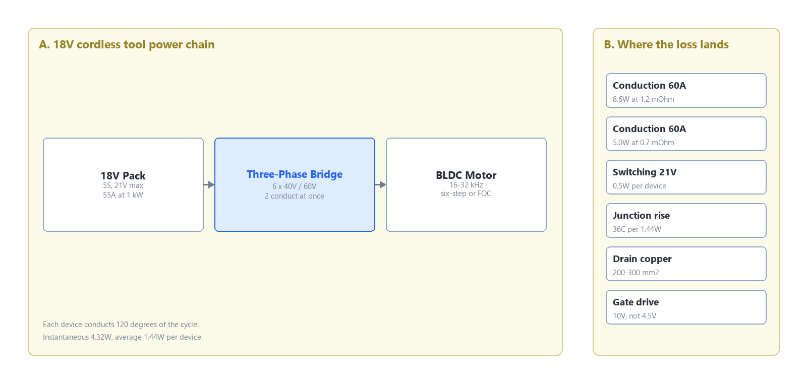
Figure 1: the three-phase bridge in an 18V tool. Conduction runs through two devices at a time, so the loss per device is one third of the instantaneous figure.
Parameter comparison
Five parts, all N-channel, voltages and currents taken from each published datasheet.
| Model | VDSS | ID | RDS(on) | Package | Position in this design |
|---|---|---|---|---|---|
| VBGED1401 | 40V | 250A | 0.7 mΩ @10V | LFPAK56 | Main bridge on 5S packs, lowest loss |
| VBGQA1401 | 40V | 150A | 1.09 mΩ @10V | DFN8(5×6) | Cost-reduced 5S bridge |
| VBGED1601 | 60V | 270A | 1.2 mΩ @10V | LFPAK56 | 6S packs and long battery leads |
| VBGQA1601 | 60V | 200A | 1.3 mΩ @10V | DFN8(5×6) | 60V bridge in a smaller footprint |
| VBGQA1606 | 60V | 80A | 6.0 mΩ @10V | DFN8(5×6) | Small motors, low continuous current |
The catalogue detail that does not appear in any comparison page: across VBsemi's published 40V and 60V families, the 40V class reaches 0.7 mΩ at 250A in LFPAK56, while the best 60V device in the same footprint is 1.2 mΩ at 270A. Twenty volts of extra rating costs 71% more conduction loss on identical copper and identical board area, which is why the pack configuration — not the price list — should choose the voltage class.
Engineering trade-offs: die, package, and the copper underneath
Conduction is 90% of the loss and it is set by RDS(on) alone. At 60A, 1.2 mΩ gives 4.32W instantaneously, and because each device conducts for 120° of the electrical cycle its average is 1.44W. Summed over the bridge that is 8.6W at any instant. Moving to the 0.7 mΩ part drops it to 5.0W. Three and a half watts recovered in a handle with no airflow is the difference between a 96°C junction and an 81°C junction at 60°C ambient, which is the difference between a five-year tool and a two-year tool.
Gate drive voltage is a hidden multiplier. VBsemi publishes RDS(on) at both 10V and 4.5V for every part in these families, and the gap is not cosmetic: VBGQA1401 is 1.09 mΩ at 10V but 1.5 mΩ at 4.5V, a 38% penalty. If the driver runs from a 5V rail to save a charge pump, the conduction budget grows by more than a third and the money saved on the driver is spent again on silicon. Drive at 10V, or accept that the RDS(on) column you selected against does not apply.
The package is a thermal component, not a container. LFPAK56 spreads heat through a large source pad and a drain clip, and its junction-to-case resistance is low enough that the PCB, not the part, becomes the limit. DFN8(5×6) is smaller and cheaper and needs 200–300 mm² of drain copper with via stitching to inner layers to reach the same junction temperature. Neither is wrong; the mistake is choosing DFN8 for the footprint and then laying out 80 mm² of copper under it.
Recommended parts: VBGED1401 (40V / 250A / 0.7 mΩ / LFPAK56) for the main bridge on 5S packs, and VBGED1601 (60V / 270A / 1.2 mΩ / LFPAK56) where the pack is 6S or the leads are long.
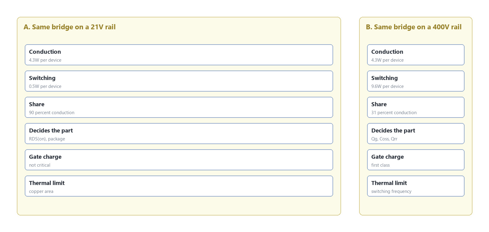
Figure 2: conduction against switching in the same bridge. At 21V the switching bars are negligible; at 400V they are the design.
Four field mistakes
- Buying 60V "for margin" on a 5S pack. 21V against 40V is a 1.9× margin; the extra class buys nothing except 71% more conduction loss, and it costs more silicon for the same RDS(on).
- Sizing on pack current instead of phase current and duty. A designer who divides 1 kW by 18V gets 55A and then treats it as continuous per device. Each device conducts one third of the time, but during that third it carries the full phase current, so the instantaneous figure — not the average — is what avalanche and SOA ratings must survive.
- Driving the gate at 4.5V. The RDS(on) quoted in the headline is a 10V number. At 4.5V these parts are 35–40% worse, and the efficiency curve moves by two points with no change to the BOM.
- Ignoring the braking event. When the trigger is released on a drill or grinder, the motor becomes a generator and the bridge sees pack voltage plus the inductive spike. Without a clamp, a 40V part on a 21V pack can be pushed past its rating in a single stop.
Where this approach stops working
Push switching above 35 kHz, as some compact drivers do to move the tone out of the audible band, and the 0.5W switching term climbs toward the conduction budget; at that point gate charge returns as a first-class parameter. Above 80A of continuous phase current, two devices must be paralleled, and then current sharing and layout dominate every datasheet number. On 10S or 36V packs the 60V class runs out of margin and 80V becomes the floor. Corded tools at 120–230Vac live on a 400V rail and follow an entirely different set of rules.
FAQ
Q: Why can't I use a 30V MOSFET on an 18V pack?
A: A 5S pack charges to 21V and braking or hot-plug transients add another 5–10V, so a 30V device is already at its limit at rest. 40V is the practical floor for a 5S tool.
Q: Is 60V always the safer choice for power tools?
A: Only when the pack is 6S or the battery leads are long enough to generate large spikes. On a 5S pack, 40V keeps a 1.9× margin and offers 0.7 mΩ against 1.2 mΩ, so 60V is a loss penalty bought for nothing.
Q: Does RDS(on) spread matter when paralleling?
A: Less than most designers expect. At 10V gate drive these parts have a positive temperature coefficient, so the device that takes more current heats up, its resistance rises, and the sharing corrects itself. A 10% RDS(on) spread produces roughly 10% current and loss imbalance, not a runaway. What does not self-correct is threshold voltage: a 300mV Vth mismatch lets one device take most of the switching transient.
Q: How much copper does a DFN8(5×6) need?
A: About 200–300 mm² of drain copper with via stitching to the inner layers. Below 100 mm² the junction temperature is set by the footprint rather than by the silicon.
Q: Do parallel devices need separate gate resistors?
A: Yes. A shared gate resistor lets the devices interact through the gate loop, and the faster one takes more current and gets hotter. Individual resistors of 2–10 Ω per device stop the oscillation.

Download PDF document
 Download now:VBGED1401


Request Free Samples
*To request free samples, please complete and submit the following information.
Our team will review your application within 24 hours and arrange shipment upon approval. Thank you!