 中文
 English

Scenario Product Guide
High-End Exhibition Reception Robot Power MOSFET Selection: VBQF3307 / VBQF2658
 Back to previous page

With the rapid evolution of service robotics and intelligent automation, high-end exhibition reception robots have become key ambassadors for interactive experiences and brand image. Their mobility, sensory processing, and human-machine interaction systems, serving as the "limbs, senses, and voice" of the platform, demand precise, efficient, and highly reliable power conversion and control for critical loads such as drive motors, high-power computing units, and safety actuators. The selection of power MOSFETs is pivotal in determining the system's dynamic response, thermal performance, operational endurance, and safety compliance. Addressing the stringent requirements of exhibition robots for efficiency, quiet operation, integration, and functional safety, this article reconstructs the power MOSFET selection logic based on scenario adaptation, providing an optimized, ready-to-implement solution.
Key Takeaways
• Three scenarios: High-Torque BLDCM Drive (150W–400W, VBQF3307), Intelligent Power Distribution & Management (VBC8338), and Safety & Interface Control (VBQF2658).
• Selection rules: provide ≥50% voltage margin on 24V/48V buses, prioritize ultra-low Rds(on) and Qg, and select DFN/TSSOP packages for power density and cooling.
• Target duty cycle: 10+ hours of daily interactive operation under vibration and frequent start-stop cycling.
Recommended Power MOSFETs at a Glance
Device | Type | VDS | Continuous Current | Rds(on) | Package | Role in This Solution |
VBQF3307 | Dual N-MOS | 30V | 30A per channel | 8mΩ @10V | DFN8(3x3)-B | High-torque BLDCM drive (Mobility Core) |
VBC8338 | Dual N+P | ±30V | 6.2A N-ch / 5A P-ch | 22mΩ N / 45mΩ P @10V | TSSOP8 | Intelligent power distribution (System Support) |
VBQF2658 | Single P-MOS | -60V | -11A | 60mΩ @10V | DFN8(3x3) | Safety & interface control (Functional Safety) |
I. Core Selection Principles and Scenario Adaptation Logic
Core Selection Principles
Voltage & Dynamic Margin: For typical power bus voltages of 24V/48V in mobile platforms, MOSFET voltage ratings must accommodate regenerative braking spikes, bus transients, and provide a safety margin ≥50%.
Ultra-Low Loss & High Frequency: Prioritize devices with ultra-low on-state resistance (Rds(on)) and gate charge (Qg) to minimize conduction and switching losses, crucial for battery life and thermal management in continuous operation.
Package for Power Density & Cooling: Select advanced packages (DFN, TSSOP) based on power level and spatial constraints within the robot's chassis, balancing high current handling with effective heat dissipation.
Reliability under Dynamic Loads: Ensure robustness against mechanical vibration, frequent start-stop cycles, and potential load surges, supporting 10+ hours of daily interactive operation.
Scenario Adaptation Logic
Based on core subsystem requirements, MOSFET applications are categorized into three primary scenarios: High-Torque BLDCM Drive (Mobility Core), Intelligent Power Distribution & Management (System Support), and Safety & Interface Control (Functional Safety). Device parameters are matched accordingly for optimized performance.
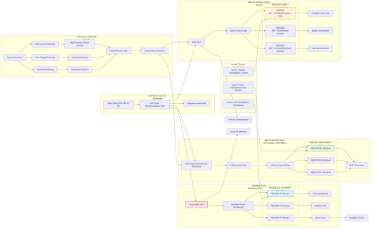
Figure 1: Overall power topology of the high-end exhibition reception robot — mobility, power distribution and functional-safety subsystems
II. MOSFET Selection Solutions by Scenario
Scenario 1: High-Torque BLDCM Drive (150W-400W) – Mobility Core Device
Recommended Model: VBQF3307 (Dual N-MOS, 30V, 30A per channel, DFN8(3x3)-B)
Key Parameter Advantages: Utilizes advanced Trench technology, achieving an exceptionally low Rds(on) of 8mΩ at 10V Vgs. A continuous current rating of 30A per channel effortlessly handles the high current demands of 24V/48V drive motors during acceleration and climbing.
Scenario Adaptation Value: The compact DFN8 package offers low parasitic inductance, essential for high-frequency PWM operation of motor inverters. Ultra-low conduction loss minimizes heat generation in the drive stage, extending battery life. The dual N-channel configuration is ideal for constructing compact three-phase bridge legs, enabling smooth, quiet, and precise motor control for agile and silent movement in exhibition halls.
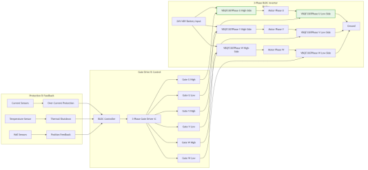
Figure 2: High-torque BLDCM drive stage (150W–400W) — VBQF3307 dual N-channel bridge leg with three-phase pre-driver and gate network
Scenario 2: Intelligent Power Distribution & Management – System Support Device
Recommended Model: VBC8338 (Dual N+P MOSFET, ±30V, 6.2A N-ch / 5A P-ch, TSSOP8)
Key Parameter Advantages: Integrated complementary pair in a single TSSOP8 package. Features low Rds(on) of 22mΩ (N-ch) and 45mΩ (P-ch) at 10V Vgs, suitable for 12V/24V auxiliary buses.
Scenario Adaptation Value: The N+P configuration enables efficient design of load switches, ideal modules for dynamic power path management. It can intelligently power cycle subsystems like the computing unit, display, or sensors based on operational modes, enhancing overall energy efficiency. The integrated package saves board space and simplifies layout for complex power distribution networks.
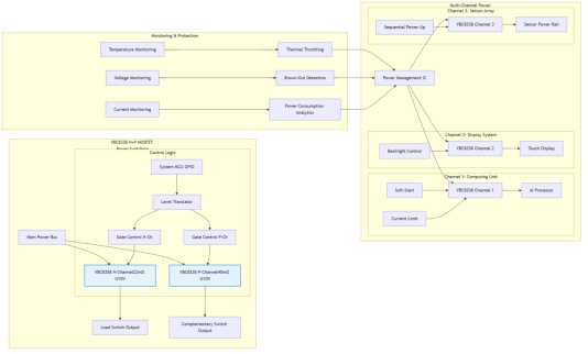
Figure 3: Intelligent power distribution and management — VBC8338 complementary N+P pair for rail switching and hot-swap load control
Scenario 3: Safety & Interface Control – Functional Safety Device
Recommended Model: VBQF2658 (Single P-MOS, -60V, -11A, DFN8(3x3))
Key Parameter Advantages: Higher voltage rating of -60V provides ample margin for 48V systems. Low Rds(on) of 60mΩ at 10V Vgs and continuous current of -11A ensure minimal drop in safety-critical paths.
Scenario Adaptation Value: The high-side P-MOSFET is perfect for implementing safe-disable functions for actuators (e.g., arm movement, base drive) or emergency stop circuits. Its -60V rating offers robust protection against voltage transients. The DFN8 package provides good thermal performance for reliable operation in fault conditions. Enables clean isolation of power to peripheral interfaces or non-essential loads during standby or fault states.
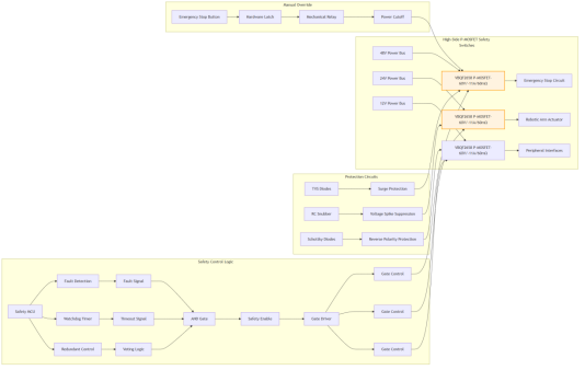
Figure 4: Safety and interface power gating — VBQF2658 P-MOS high-side switch for emergency stop and actuator safe-disable
III. System-Level Design Implementation Points
Drive Circuit Design
VBQF3307: Requires a dedicated three-phase pre-driver or motor driver IC. Optimize gate drive loop layout to minimize ringing. Ensure sufficient gate drive current for fast switching.
VBC8338: Can be driven by GPIOs of system PMIC or MCU for lower frequency switching. Consider separate gate resistors for N and P channels.
VBQF2658: Use a simple NPN transistor or small N-MOSFET for level translation and gate control. Incorporate RC snubber if necessary to dampen transients.
Thermal Management Design
Graded Strategy: VBQF3307 requires significant PCB copper pour, potentially coupled to the chassis or internal heat spreader. VBC8338 and VBQF2658 can rely on package thermal pads and local copper for heat dissipation.
EMC and Reliability Assurance
Protection Measures: Integrate hardware-based overcurrent detection and fast-acting fuses in motor and main power paths. Utilize TVS diodes at all input power ports and near MOSFET drains for surge and ESD protection. Ensure robust mechanical mounting to withstand vibration.
IV. Core Value of the Solution and Optimization Suggestions
The scenario-adapted power MOSFET selection solution for high-end exhibition reception robots achieves comprehensive coverage from core propulsion to intelligent power management and functional safety. Its core value is reflected in three key aspects:
Frequently Asked Questions (FAQ)
Q: Which device is recommended for the high-torque BLDCM drive stage?
A: VBQF3307 (Dual N-MOS, 30V, 30A per channel, DFN8(3x3)-B) — an 8mΩ Rds(on) at 10V and dual N-channel configuration are ideal for building compact three-phase bridge legs with smooth, quiet and precise motor control.
Q: Which device handles intelligent power distribution and management?
A: VBC8338 (Dual N+P MOSFET, ±30V, 6.2A N-ch / 5A P-ch, TSSOP8) — the integrated complementary pair enables efficient load switches and dynamic power path management for 12V/24V auxiliary buses.
Q: Which device implements the safety and emergency-stop function?
A: VBQF2658 (Single P-MOS, -60V, -11A, DFN8(3x3)) — the -60V high-side P-MOSFET provides ample margin for 48V systems and is perfect for safe-disable functions and emergency stop circuits.

Download PDF document
 Download now:VBQF3307


Request Free Samples
*To request free samples, please complete and submit the following information.
Our team will review your application within 24 hours and arrange shipment upon approval. Thank you!