 中文
 English

Scenario Product Guide
Industrial Park Energy Storage Cluster Power MOSFET Selection: VBPB18R47S / VBQG
 Back to previous page
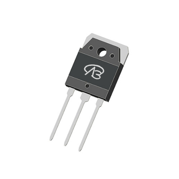
With the acceleration of global energy transition and the rise of smart grids, energy storage clusters in high-end industrial parks have become critical infrastructure for ensuring power quality, stabilizing the grid, and managing peak loads. Their power conversion systems (PCS, BMS, auxiliary power), serving as the core for energy flow control, directly determine the cluster's round-trip efficiency, power density, operational lifespan, and safety. The power MOSFET, a key switching component in these systems, profoundly impacts overall performance, reliability under extreme conditions, and total cost of ownership through its selection. Addressing the high-voltage, high-current, continuous operation, and stringent reliability demands of industrial energy storage, this article proposes a complete, actionable power MOSFET selection and design implementation plan with a scenario-oriented and systematic approach.
Key Takeaways
• Three subsystems: Main Power Conversion (PCS, VBPB18R47S 800V), Battery Management & Balancing (VBQG3322 dual N+N), and Auxiliary Power & Protection (VBGMB1103 100V/80A).
• Selection rules: 30–50% voltage margin on 600–800V battery-stack buses, low Rds(on) with low Qg/Coss, and packages matched to thermal design (TO-247/TO-3P/TO-220F vs DFN/SC75/SOP8).
• Expansion options: VBMB165R42SFD (650V/42A/56mΩ, TO220F) for higher PCS power density, and VBA4338 (Dual-P+P, -30V/-7.3A, SOP8) for high-side disconnect switching.
Recommended Power MOSFETs at a Glance
Device | Type | VDS | Continuous Current | Rds(on) | Package | Role in This Solution |
VBPB18R47S | Single-N (SJ_Multi-EPI) | 800V | 47A | 90mΩ @10V | TO3P | PCS bidirectional DC/AC inverter & DC/DC converter switch |
VBQG3322 | Dual N+N | 30V | 5.8A per channel | 22mΩ @10V | DFN6(2x2)-B | BMS active cell balancing & pack switching |
VBGMB1103 | Single-N (SGT) | 100V | 80A | 2.9mΩ @10V | TO220F | Contactor drive & auxiliary power switch |
I. Overall Selection Principles: Balancing High Voltage, Low Loss, and Maximum Reliability
High Voltage Margin & Ruggedness: Based on DC bus voltages (commonly 600V–800V for battery stacks, 150V–400V for sub-modules), select MOSFETs with a voltage rating margin of ≥30–50% to handle switching spikes, voltage ringing, and grid-side transients. Devices must exhibit excellent avalanche energy rating and dv/dt capability.
Ultra-Low Loss for High Efficiency: Loss directly impacts system efficiency and cooling overhead. Prioritize devices with minimal specific on-resistance (Rds(on)) to reduce conduction loss. For high-frequency switching applications, low gate charge (Qg) and low output capacitance (Coss) are critical to minimize switching loss and enable higher switching frequencies for increased power density.
Package for Power & Thermal Management: Select packages based on power level and thermal design requirements. High-power main circuits (>kW) demand packages with very low thermal resistance and high current capability (e.g., TO-247, TO-3P, TO-220F). For highly integrated, space-constrained auxiliary circuits, compact packages (e.g., DFN, SC75, SOP8) are preferred.
Industrial-Grade Reliability: Designed for 24/7 operation, focus must be on a wide operating junction temperature range (preferably up to 175°C), high robustness against surge currents, and stable parameters over lifetime under thermal cycling stress.
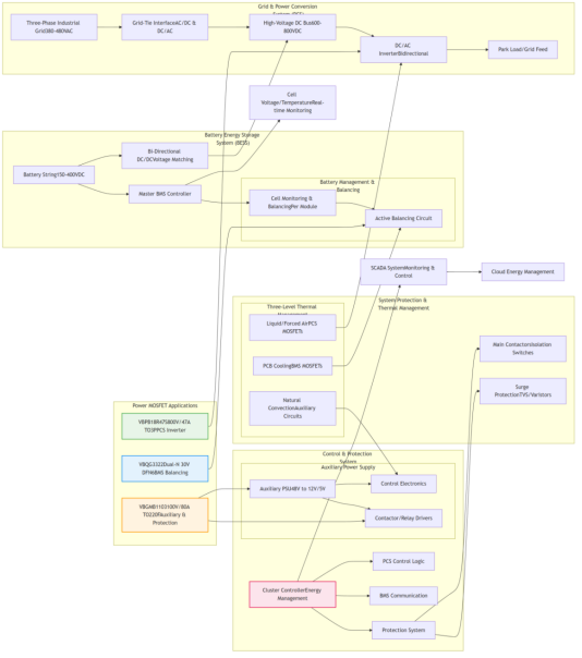
Figure 1: Overall power topology of the industrial park energy storage cluster — PCS, BMS and auxiliary power subsystems
II. Scenario-Specific MOSFET Selection Strategies
Scenario 1: Main Power Conversion System (PCS) – DC/AC Inverter & DC/DC Converter (Power Level: 10s to 100s of kW)
Recommended Model: VBPB18R47S (Single-N, 800V, 47A, TO3P)
Ultra-high 800V drain-source voltage (VDS) rating, providing ample margin for 600V–650V DC bus systems.
Utilizes advanced SJ_Multi-EPI (Super Junction) technology, offering an excellent balance of low Rds(on) (90 mΩ @10V) and high voltage capability, minimizing conduction loss.
TO3P package provides superior thermal performance and mechanical rigidity for high-power applications.
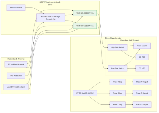
Figure 2: Main power conversion system (PCS) — VBPB18R47S (800V, TO3P) in the bidirectional DC/AC inverter and DC/DC converter
Scenario 2: Battery Management System (BMS) – Active Cell Balancing & Pack Switching
Recommended Model: VBQG3322 (Dual-N+N, 30V, 5.8A per channel, DFN6(2x2)-B)
Dual N-channel integration in a tiny DFN6(2x2) package, saving significant board space in multi-channel BMS designs.
Low Rds(on) (22 mΩ @10V) ensures minimal voltage drop and power loss during balancing operations.
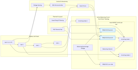
Figure 3: Battery management system (BMS) — VBQG3322 dual N-channel devices in active cell balancing and pack switching
Scenario 3: Auxiliary Power & System Protection Circuits (PSU, Contactor Drive, Surge Protection)
Recommended Model: VBGMB1103 (Single-N, 100V, 80A, TO220F)
Utilizes SGT (Shielded Gate Trench) technology, achieving an exceptionally low Rds(on) of 2.9 mΩ @10V, leading to minimal conduction loss.
High continuous current rating (80A) is ideal for driving inductive loads like contactors or serving as the main switch in auxiliary DC-DC converters.
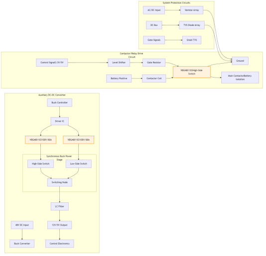
Figure 4: Auxiliary power and protection circuits — VBGMB1103 (100V/80A) contactor drive and auxiliary DC-DC stage
III. Key Implementation Points for System Design
Drive Circuit Optimization:
High-Voltage MOSFETs (e.g., VBPB18R47S): Employ isolated gate drivers with high peak current (>2A) and negative turn-off voltage to ensure fast, robust switching and prevent spurious turn-on.
Integrated Multi-Channel MOSFETs (e.g., VBQG3322): Ensure independent gate drive paths to avoid cross-coupling. Use RC filters on gate signals in noisy environments.
Advanced Thermal Management:
Implement a tiered strategy: liquid cooling or large finned heatsinks for TO-3P/TO-247 devices (main inverter); PCB copper pours + thermal vias for TO-220F; and natural convection for compact packages in BMS.
Strict derating: Ensure operating junction temperature remains below 110°C–125°C for extended lifetime.
IV. Solution Value and Expansion Recommendations
Maximized Energy Throughput: The combination of SJ and SGT technologies in key positions achieves system-level efficiencies >98%, directly reducing operating costs.
Mission-Critical Reliability: Devices selected for high voltage margins, low thermal resistance, and industrial-grade robustness ensure 24/7 operation with minimal downtime.
Optimization and Adjustment Recommendations:
Higher Power Density: For next-generation ultra-compact PCS, consider using VBMB165R42SFD (650V, 42A, 56mΩ, TO220F) in parallel configurations or as a stepping stone to full SiC solutions.
Enhanced Protection: For critical high-side disconnect switches, VBA4338 (Dual-P+P, -30V, -7.3A, SOP8) offers integrated fault channel isolation in a compact form factor.
The selection of power MOSFETs is a cornerstone in designing efficient and reliable energy storage cluster systems. The scenario-based selection and systematic design methodology proposed herein aim to achieve the optimal balance among efficiency, power density, scalability, and ultra-high reliability. As wide-bandgap semiconductor technology matures and costs decline, its integration will pave the way for the next generation of grid-edge energy storage solutions, providing robust hardware support for the stable and efficient operation of industrial park power systems.
Frequently Asked Questions (FAQ)
Q: Which device is recommended for the main power conversion system (PCS)?
A: VBPB18R47S (Single-N, 800V, 47A, TO3P) — the ultra-high 800V VDS rating provides ample margin for 600V–650V DC buses, and SJ_Multi-EPI technology balances a 90mΩ Rds(on) at 10V with high blocking capability.
Q: Which device is recommended for battery management and cell balancing?
A: VBQG3322 (Dual-N+N, 30V, 5.8A per channel, DFN6(2x2)-B) — dual N-channel integration in a tiny DFN6 package saves board space in multi-channel BMS designs, with a 1.7V threshold enabling direct GPIO drive.
Q: Which device drives contactors and auxiliary power?
A: VBGMB1103 (Single-N, 100V, 80A, TO220F) — SGT technology delivers a 2.9mΩ Rds(on) at 10V, ideal for driving high-current contactors or serving as the main switch in auxiliary DC-DC converters.

Download PDF document
 Download now:VBPB18R47S


Request Free Samples
*To request free samples, please complete and submit the following information.
Our team will review your application within 24 hours and arrange shipment upon approval. Thank you!