 中文
中文 English
Scenario Product Guide
2026 Humanoid Robot Power Semi Select Guide: MOSFET Pract. HV Joints-MicroAct
 Back to previous page
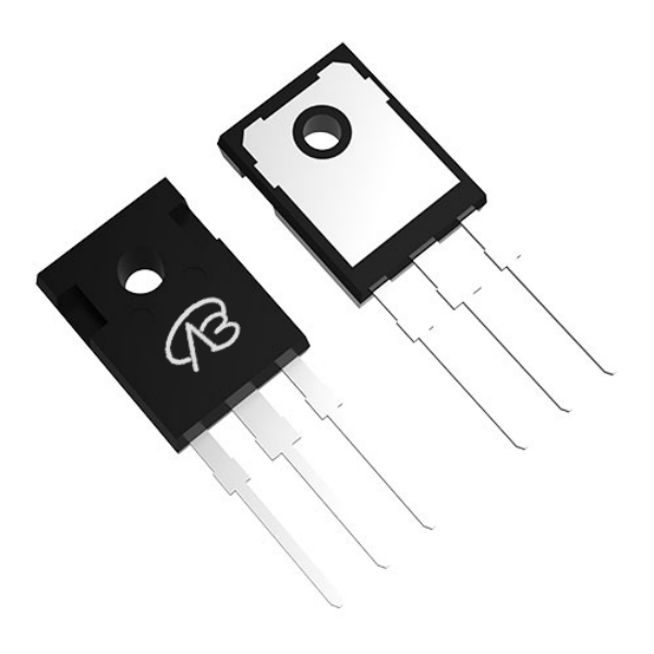
The Evolution and Challenges of Power Semiconductors for Humanoid Robots in 2026
By 2026, humanoid robots are moving from laboratory prototypes to large-scale commercial use. With the accelerated deployment of products like the Tesla Optimus Gen-3 and Figure 02 in factories, logistics, and home services, OEMs are placing unprecedentedly stringent demands on the power density, dynamic response, and reliability of core modules such as joint actuators, power management, and energy recovery. As the key carriers of a robot's "muscles" and "nerves," the selection of power MOSFETs is no longer a simple matter of parameter matching. It requires coordinated thermal management, control algorithms, and safety redundancy at the system level to achieve high-frequency, high-torque output for humanoid movements and stable operation throughout its entire lifecycle.
Meanwhile, the application of wide-bandgap semiconductors (SiC, GaN) in ultra-high power joints is maturing, and intelligent power modules (IPMs) and highly integrated SGT devices are reshaping the design paradigm of low-voltage, high-density drivers. Based on the latest device technology advancements up to 2026 and the actual needs of the robotics industry, this article systematically outlines the MOSFET selection principles for various functional modules of humanoid robots, covering the complete power chain from high-voltage hip joint drives to micro-actuators in finger joints. Combining typical models and topologies, it provides engineers with a forward-looking and engineering-practical selection guide.
Humanoid robot systems are complex, and different functional modules have significantly different requirements for power devices, requiring precise selection based on specific scenarios.
I. Core Selection Principles
The selection of MOSFETs for humanoid robots should follow the following four-dimensional collaborative adaptation principles:
Dimensions | Key Requirements |
Voltage Margin | A 50% to 100% margin should be reserved in the withstand voltage value to cope with back EMF, PWM spikes, and regenerative braking. |
Low loss | Extremely low Rds(on) reduces conduction losses, and low Qg/Coss supports high-frequency PWM (20-100kHz) |
Package matching | For high-power applications, choose TO-247/TO-220; for space-constrained applications, choose DFN/SOT23 |
Reliability | Wide junction temperature range, high ESD tolerance, shock resistance, supports frequent start-stop cycles |
II. Module Selection Recommendations
1. Joint motor drive module (power core)
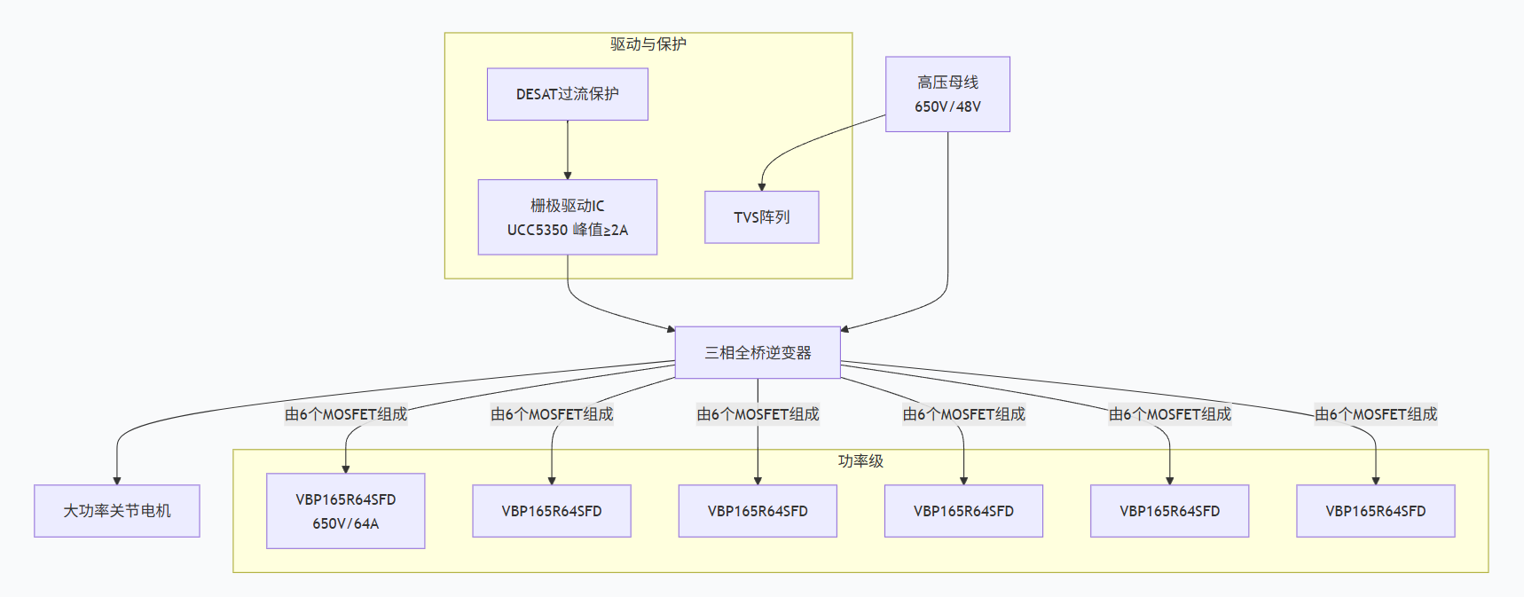
This is the most critical power component for humanoid robots, and it is divided into two categories based on joint power levels:
High-power joints (hip, knee, shoulder, etc., peak power > 10kW)
Parameters | Recommended Models | Specifications and Features |
Main switching transistor | VBP165R64SFD | 650V/64A/36mΩ,TO-247 Package,SJ_Multi-EPI Technology |
Low voltage, high current | VBGQF1402 | 40V/100A/2.2mΩ,DFN8(3×3),SGT |
High torque density | VBGQA1102N | 100V/30A/18mΩ,DFN8(5×6),Compatible with 48-60V systems |
Selection criteria: Must support millisecond-level torque response, and be compatible with a high-speed gate driver IC (such as UCC5350), with a drive current ≥2A.
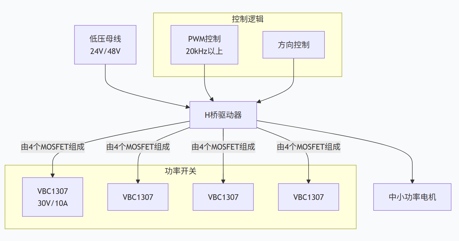
Small to medium power joints (elbow, wrist, ankle, etc., power 20W-150W)
Parameters | Recommended Models | Specifications and Features |
Universal type | VBC1307 | 30V/10A/7mΩ,TSSOP8,Supports PWM above 20kHz |
High cost performance | VB7430 | 40V/6A/25mΩ,SOT23-6,Supports parallel connection of multiple transistors |
48V system | VBB1630 | 60V/5.5A,Higher withstand voltage margin |
2. Power Management and Distribution Module (Energy Hub)
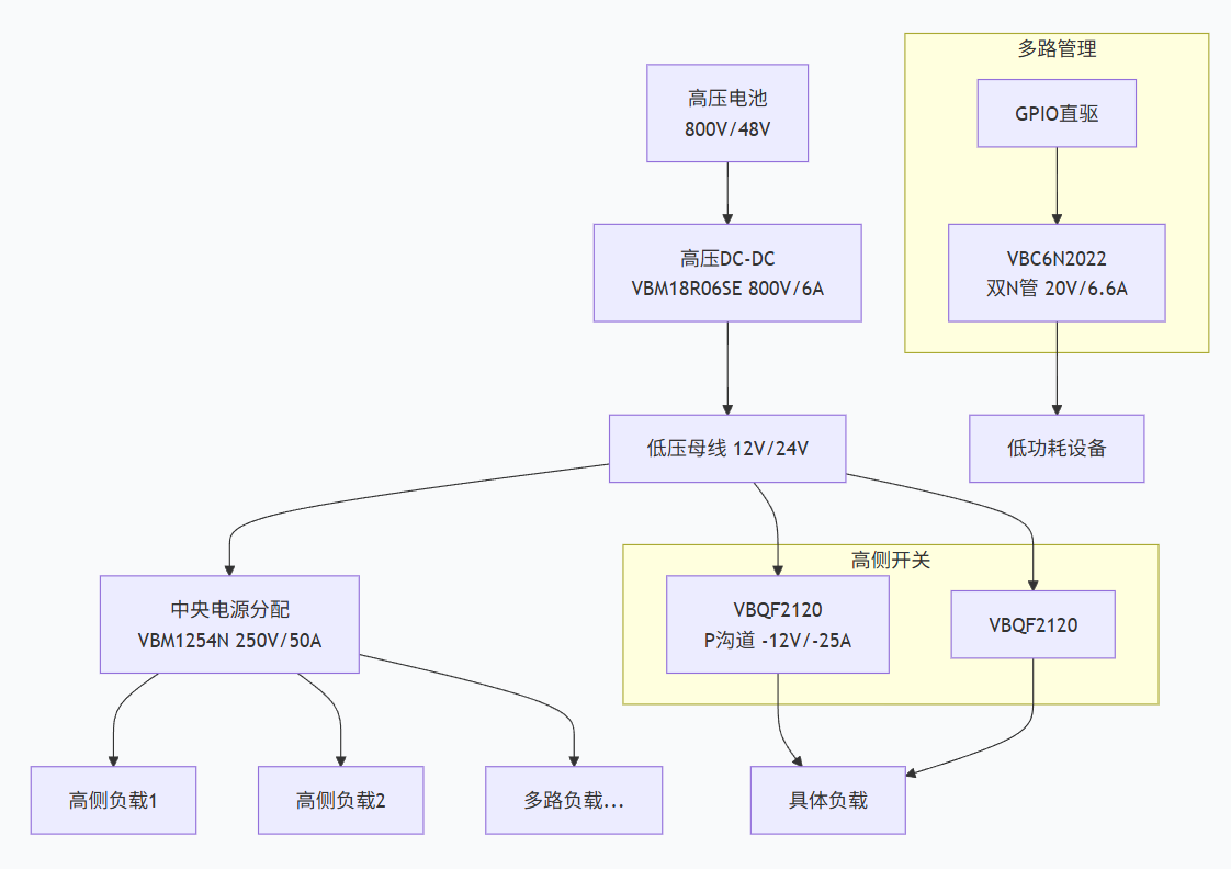
Functional Scenarios | Recommended Models | Specifications and Features |
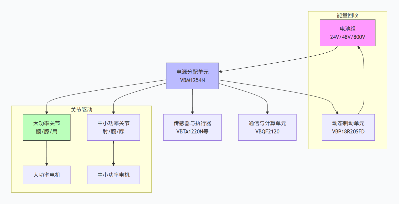
Central Power Distribution | VBM1254N | 250V/50A/41mΩ, TO-220, 5 times voltage margin |
High-Voltage DC-DC/PFC | VBM18R06SE | 800V/6A, TO-220, Super Junction technology |
High-Side Power Switch | VBQF2120 | -12V/-25A/15mΩ, DFN8(3×3), P Channel |
Multi-Load Management | VBC6N2022 | 20V/6.6A, TSSOP8, dual N-transistor integrated, GPIO direct drive |
3. Dynamic braking and energy recovery module
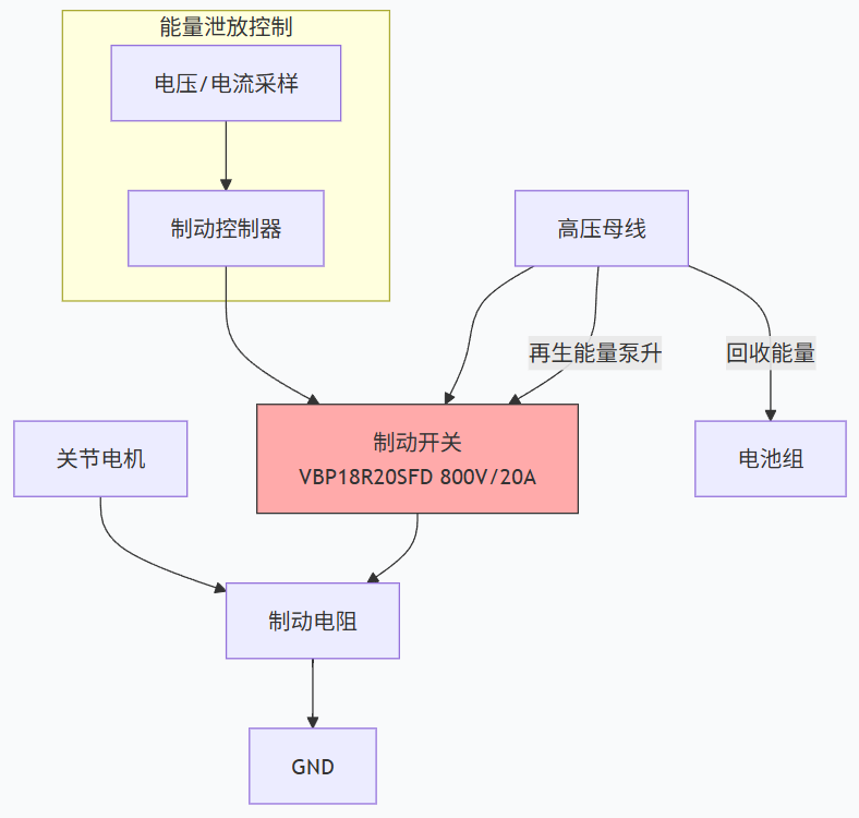
Parameters | Recommended Models | Application Scenarios |
Brake switch | VBP18R20SFD | 800V/20A/205mΩ, TO-247, for handling voltage boost |
Energy Discharge | VBMB17R07SE | 700V/7A, adaptable to harsh environments |
4. Sensor and actuator drive module (nerve endings)
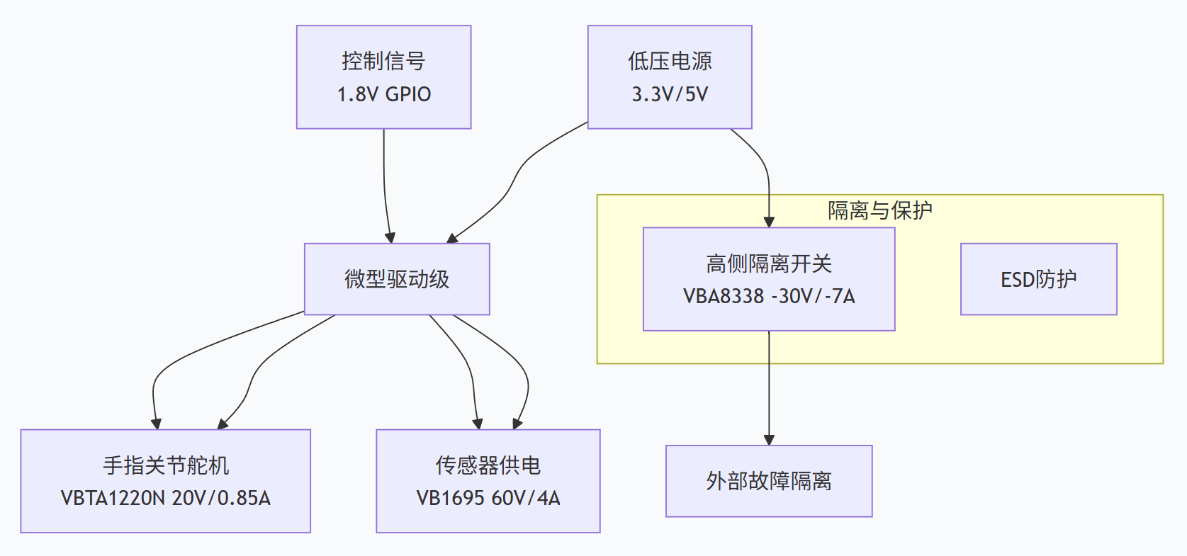
Parameters | Recommended Models | Application Scenarios |
Miniature servo motor/finger joint | VBTA1220N | 20V/0.85A, SC75-3, 1.8V GPIO direct drive |
Sensor power management | VB1695 | 60V/4A, fine power control |
High-side isolation switch | VBA8338 | -30V/-7A/18mΩ, MSOP8, fault isolation |
5. Power supply for communication and computing units
Parameters | Recommended Models | Features |
Core processor power supply | VBQF2120 | Ultra-low on-resistance, dynamic power supply |
Intelligent power distribution | VBFB1311 | 30V/50A, dual P-MOS integrated, DFN8 |
III. Key Considerations for System Integration Design
Thermal Management Strategies
High-Power Devices (VBP165R64SFD): Requires liquid cooling or a large heatsink, with real-time case temperature monitoring.
Medium-Power Devices (VBM1254N): PCB copper plating for heat dissipation + airflow design.
Miniature Packages (VBTA1220N): Relies on air convection.
Drive Circuit Design
High-Speed Drive: Joint drive requires a peak drive current of ≥2A to shorten switching time.
Protection Mechanisms: Gate series resistor (22Ω), TVS diode protection, hardware overcurrent protection (DESAT).
EMC Suppression: Parallel RC snubber circuit, power ground and signal ground single-point connection.
Reliability Assurance
Derating Design: Voltage and current maintain a margin of over 30%
Surge Protection: Varistors/TVS arrays are configured at the bus terminals
Predictive Maintenance: Temperature sensors are embedded in critical components to monitor thermal cycling
IV. Selection Quick Reference Table
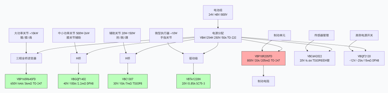
Module | Power Rating | Preferred Model | Package | Key Parameters |
Main joint drive | >10kW | VBP165R64SFD | TO-247 | 650V/64A/36mΩ |
Main joint drive | 500W-2kW | VBGQF1402 | DFN8(3×3) | 40V/100A/2.2mΩ |
Auxiliary joints | 20W-150W | VBC1307 | TSSOP8 | 30V/10A/7mΩ |
Finger/micro-joints | <10W | VBTA1220N | SC75-3 | 20V/0.85A |
Power distribution | Medium power | VBM1254N | TO-220 | 250V/50A/41mΩ |
Braking Energy Recovery | Safety critical | VBP18R20SFD | TO-247 | 800V/20A |
Sensor management | Low power consumption | VBC6N2022 | TSSOP8 | 20V/6.6A dual transistor |
High-side switch | Power path | VBQF2120 | DFN8(3×3) | -12V/-25A/15mΩ |
V. Future Trends
For next-generation high-performance humanoid robots, the following should be considered:
SiC MOSFETs: Achieving higher switching frequencies and efficiency in >20kW super joints
Intelligent Power Modules (IPMs): High integration of drive, MOSFET, and protection functions
GaN Devices: Ultra-high frequency applications, further reducing the size of passive components
The above solutions cover the complete power chain from the high-voltage power core to the low-voltage nerve endings, and can be flexibly combined according to the specific robot's degree of freedom (e.g., 31 degrees of freedom), bus voltage (24V/48V/800V), and power level.

Download PDF document
 Download now:VBGQF1402


Request Free Samples
*To request free samples, please complete and submit the following information.
Our team will review your application within 24 hours and arrange shipment upon approval. Thank you!