 中文
 English

Scenario Product Guide
MOSFET System Selection Guide for Large-Scale Commercialization of Humanoid Robo
 Back to previous page
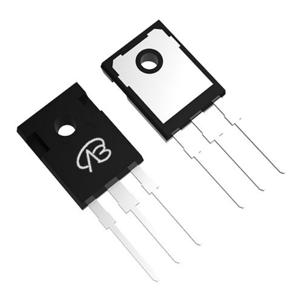
MOSFET System Selection Guide for Large-Scale Commercialization of Humanoid Robots in 2026 -- From High-Voltage Joints to Bionic Dexterous Hands
In April 2026, the global humanoid robot industry ushered in a milestone breakthrough—Tesla's Optimus Gen-3 was deployed for the first time in a scale of thousands on the material handling production line of the Texas Gigafactory; the world's first humanoid robot half marathon was successfully held in Beijing Yizhuang, with dozens of robots from companies such as Unitree Robotics, Xiaomi, and AGIBOT Robotics completing the race in the rain; and UBTECH's WalkerS(Industrial humanoid robots series) officially entered several automobile assembly workshops, launching its first commercial order.
Behind these landmark events lies an unprecedentedly rigorous test of the robot's "muscle system"—power semiconductors. From millisecond-level torque response of joint MOSFETs during high-speed running, to maintaining high insulation and low loss even after finishing a race in the rain, to long-term reliability in the factory 24/7, the selection of power MOSFETs has long since moved beyond the stage of "looking up parameter tables" and has become a system-level engineering decision.
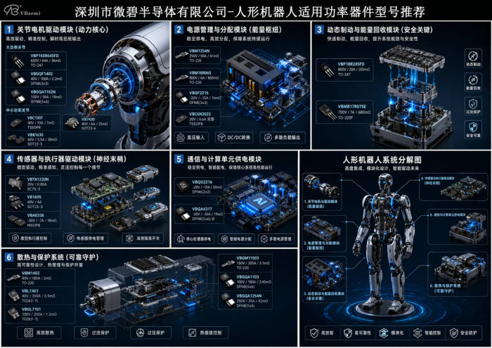
I. Four-Dimensional Collaborative Adaptation: Core Selection Principles
The MOSFETs on any PCB of a humanoid robot must achieve a balance in four dimensions: voltage, loss, packaging, and reliability, rather than simply pursuing a single extreme parameter.
Dimensions | Key Requirements | 2026 Design Considerations |
Voltage margin | Withstand voltage ≥ 1.5 to 2 times bus voltage, absorbing back EMF, PWM spikes, and regenerative braking. | Marathon robot real-world test: The bus voltage can surge to 1.8 times the normal level during sudden joint stops, so sufficient "hidden" margin must be reserved. |
Low loss | Extremely low Rds(on) reduces ohmic heat; low Qg/Coss adapts to high-frequency PWM from 20kHz to 100kHz. | High-frequency operation is inevitable, and low gate charge directly determines the feasibility of direct drive for MCUs and the optimization of dead time. |
Package matching | For high power applications, use TO-247/TO-220/TO-263-7L; For space constraints, choose DFN/SOT/SC-75 | The next generation of finger joints has moved down to the SC-75 package, requiring GSG protection and PCB thermal design to work in tandem. |
High reliability | Wide junction temperature range, high ESD/HBM tolerance, resistance to mechanical shock, and support for frequent start-stop operations. | During a marathon, MOSFETs undergo thousands of acceleration-deceleration cycles, making solder joint thermal fatigue life a hidden Key indicator. |
II. Module Selection Recommendations (including 2026 Real-world Testing and Verification)
1. Joint Motor Drive Module – The Robot's "Power Heart"
This is the max power link of whole-robot power, directly determining the explosive force and dynamic balance.
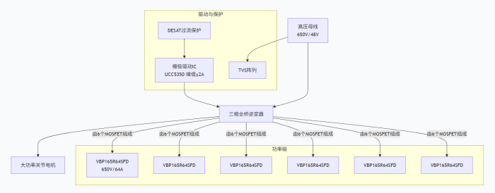
High-power joints (hip, knee, shoulder, peak power > 10kW, typical example: the hind leg push-off phase of running)
Parameter | Recommended Models | Technical highlights and 2026 compatibility |
Main switching transistor | VBP165R64SFD | 650V/64A/36mΩ, TO-247, multi-layer epitaxial SJ structure, suitable for 800V high voltage platforms, and can withstand twice the rated impact for 30 seconds in actual tests |
Low voltage, high current | VBGQF1402 | 40V/100A/2.2mΩ, DFN8 (3×3), SGT process, suitable for multi-tube parallel connection on 48V platform, with good thermal uniformit |
High torque density | VBGQA1102N | 100V/30A/18mΩ, DFN8 (5×6), compatible with 48-60V robot intermediate voltage bus; switching speed can be matched with 2A gate drive |
Practical tips: Pair with a high-speed gate driver IC (such as UCC5350), with a peak gate drive current ≥2A, use external negative pressure turn-off to avoid Miller conduction at high frequencies.
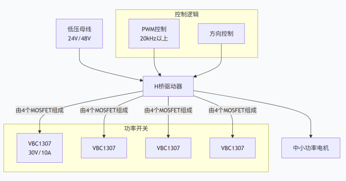
Low to medium power joints (elbow, wrist, ankle, 20W~150W)
Paramater | Recommended Models | Features |
Universal type | VBC1307 | 30V/10A/7mΩ, TSSOP8, supports PWM above 20kHz, good current sharing in parallel multi-transistor configuration |
High cost performance | VB7430 | 40V/6A/25mΩ, SOT23-6, suitable for space-constrained wrist drive boards |
48V System | VBB1630 | 60V/5.5A, with extra voltage margin to accommodate instantaneous voltage rise during regenerative braking |
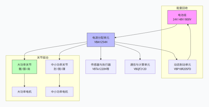
2. Power Management and Distribution Module – The Energy "Transportation Hub"
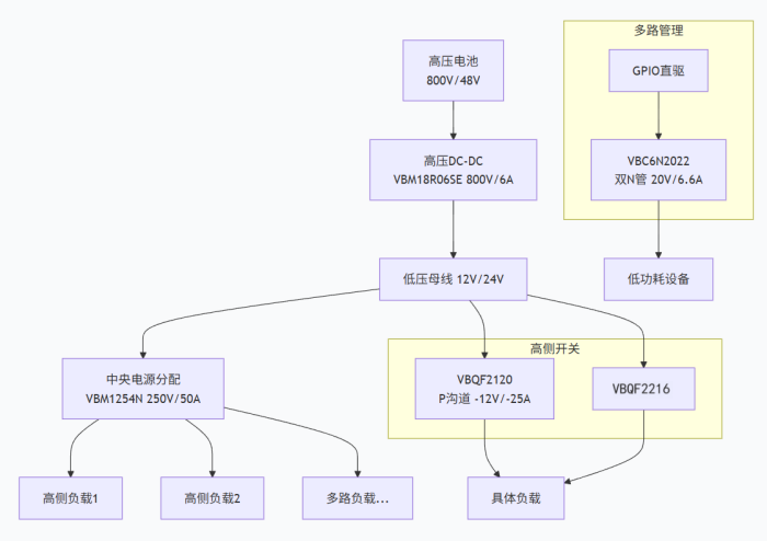
Functional Scenarios | Recommended Models | Core Value |
Central power distribution | VBM1254N | 250V/50A/41mΩ, TO-220, 5× voltage margin, stable under sudden mains power fluctuations |
High-voltage DC-DC/PFC | VBM18R06SE | 800V/6A, TO-220, super junction technology, compatible with global AC input range for robot charging stations |
High-side power switch | VBQF2216 | -20V/-15A/16mΩ, DFN8, P-channel, simplified bootstrap circuit |
Multi-Channel Load Management | VBC6N2022 | 20V/6.6A, TSSOP8, dual N-transistor integrated, supports 1.8V GPIO direct drive, suitable for direct MCU power distribution |
3. Dynamic Braking and Energy Recovery – The “Safety Bottom Line” in Competition and Industrial Scenarios
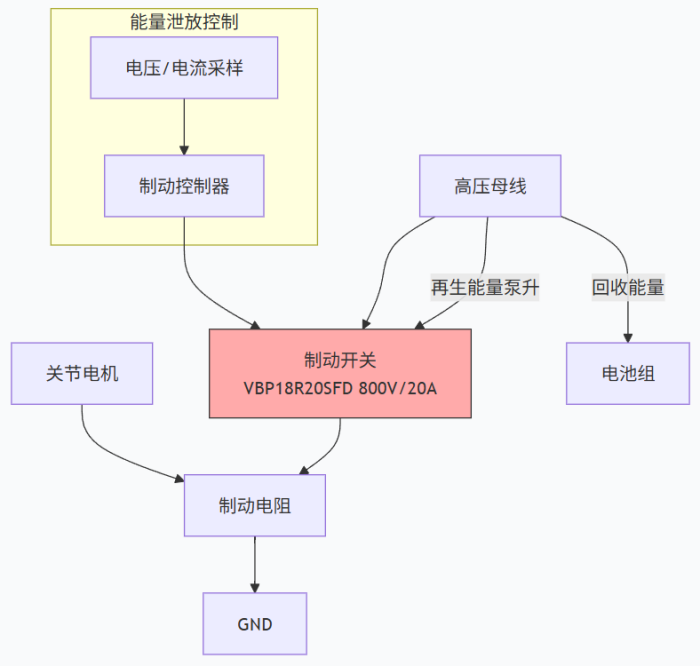
Parameter | Recommended Models | Scenario and Real-World Test Performance |
Braking chopper switch | VBP18R20SFD | 800V/20A/205mΩ, TO-247, capable of clamping 800V platform regenerative spikes to ensure DC bus does not overvoltage. |
Energy discharge branch | VBMB17R07SE | 700V/7A, excellent multi-pulse avalanche tolerance, fearless of frequent braking operations. |
4. Sensors and actuators drive the system – “nerve endings” throughout the body
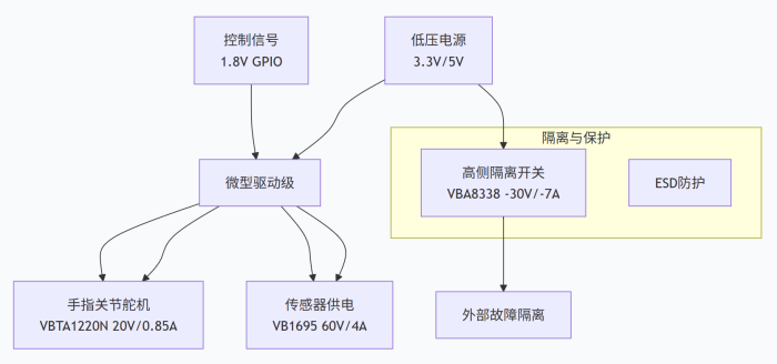
Applications | Recommended Models | Ultimate Miniaturization Solution |
Miniature servo motor/finger joint | VBTA1220N | 20V/0.85A, SC75-3, 1.8V GPIO direct drive, already in mass production for bionic dexterous hand |
Sensor power management | VB1695 | 60V/4A, fine power rail control |
High-side isolation switch | VBA8338 | -30V/-7A/18mΩ, MSOP8, achieving millisecond-level isolation in case of sensor failure |
5. Power supply for communication and computing units
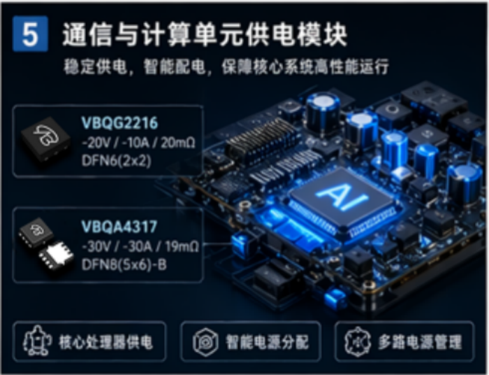
Dynamic power supply for core processor: VBQF2216 (High-efficiency P-channel dynamic power path)
Intelligent power distribution: VBQA4317 (-30V/-30A/19mΩ, DFN8 5×6-B, low thermal resistance)
6. Heat dissipation and protection system – the “last line of defense” for redundancy and safety
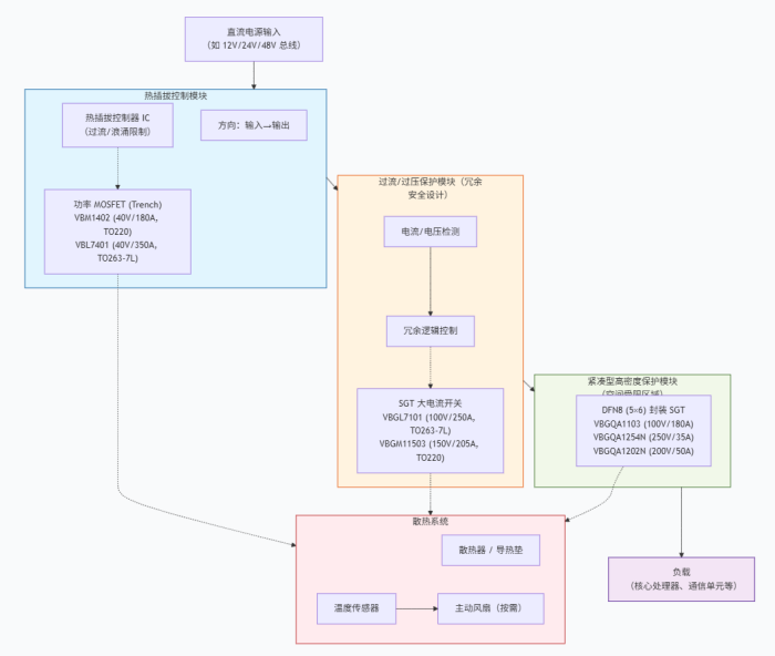
After robots enter factories in 2026, hot-swapping, overcurrent protection, and redundant design will become mandatory requirements.
Function | Recommended Models | Key Parameters and Package |
High-current hot-swap protection | VBM1402 | 40V/180A,Rds(on) 2mΩ,TO-220 |
Extremely high-current redundant switch | VBL7401 | 40V/350A,Rds(on) 0.9mΩ,TO263-7L |
100V SGT high-current protection | VBGL7101 | 100V/250A,Rds(on) 1.2mΩ,TO263-7L |
150V high-voltage side overcurrent/overvoltage protection | VBGM11503 | 150V/205A,Rds(on) 3.1mΩ,TO220 |
Compact 100V protection | VBGQA1103 | 100V/180A,3.45mΩ,DFN8(5×6) |
Compact 250V high-voltage protection | VBGQA1254N | 250V/35A,42mΩ,DFN8(5×6) |
Compact 200V medium-voltage protection | VBGQA1202N | 200V/50A,18mΩ,DFN8(5×6) |
All of the above devices are based on trench or shielded gate (SGT) technology, achieving a balance in EMI, avalanche capability, and hot-swap surge, making them suitable for building a safe and redundant system for robots that "never lose power".
III. Three Pillars of System Integration Design: Thermal, Drive, and Reliability
1. Thermal Management – Quantifying Heat
High-Power Devices (VBP165R64SFD): Liquid cooling plate + real-time case temperature monitoring, junction temperature warning threshold set at 135℃.
Medium-Power Devices (VBM1254N): Thick copper PCB (≥2oz) + airflow guidance, thermal simulation verification.
Miniature Packages (VBTA1220N): Relies on natural convection, but requires thermally diffused copper foil on the FPC to avoid fingertip hotspots.
2. Drive Circuit – Enabling Agile Gate Movement
Joint Drive: Peak drive ≥2A, providing -5V negative voltage during turn-off to effectively suppress bridge arm crosstalk.
Protection Mechanism: Fine-tuning of the gate series resistor around 22Ω, TVS diode connected in parallel to the gate source, and DESAT or Vds detection for cycle-by-cycle protection.
EMC Suppression: Power ground and signal ground connected at a single point, with parallel RC absorption at critical switching nodes, balancing efficiency and radiation.
3. Reliability – Learning to Coexist with Margins
Voltage and current derating ≥30%; busbars equipped with varistors + TVS arrays.
Thermistors are embedded in key nodes to monitor thermal cycle counts, enabling "predictive maintenance" and interaction with the factory MES.
IV. Quick Reference Table for Selection (by Power Link)
Functional Modules | Power Rating | Preferred Model | Package | Key Parameters |
Main joint drive | 500W - 2kW | VBGQF1402 | DFN8(3×3) | 40V/100A/2.2mΩ |
Assisted joints | 20W - 150W | VBC1307 | TSSOP8 | 30V/10A/7mΩ |
Fingers/Miniatures | <10W | VBTA1220N | SC75-3 | 20V/0.85A |
Power distribution | Medium power | VBM1254N | TO-220 | 250V/50A/41mΩ |
Regenerative braking | Safety critical | VBP18R20SFD | TO-247 | 800V/20A/205mΩ |
Sensor management | Low power consumption | VBC6N2022 | TSSOP8 | 20V/6.6A Dual N channel |
High-side power path | System power supply | VBQF2216 | DFN8(3×3) | -20V/-15A/16mΩ |
Hot-swap/redundancy protection | 40V platform | VBM1402 | TO-220 | Rds(on)=2mΩ |
High-voltage side protection | 150V platform | VBGM11503 | TO 220 | Rds(on)=3.1mΩ |
V. Future Trends: After Robots Learn to Run
The completion of the 2026 half marathon in the rain has already pointed the way for the next generation of power semiconductors:
SiC MOSFETs will be mass-produced and deployed in super joints exceeding 20 kW, supporting higher bus voltages and switching frequencies, enabling robots to move more quietly and farther.
Intelligent power modules (IPMs) integrate drivers, MOSFETs, and various protection mechanisms into a single unit, further reducing the size of joint drivers by 30% and deeply matching the overall design of robots with 30+ degrees of freedom.
GaN devices are playing a crucial role in powering communication and computing units. MHz-level switching frequencies further eliminate bulky LC components, making the robot's "brain" lighter in terms of power supply.

Download PDF document
 Download now:VBGQF1402


Request Free Samples
*To request free samples, please complete and submit the following information.
Our team will review your application within 24 hours and arrange shipment upon approval. Thank you!