
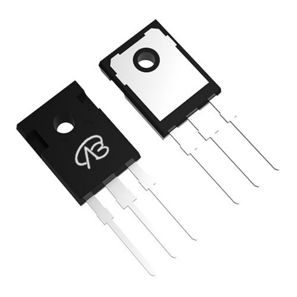
Against the backdrop of the deep integration of the low-altitude economy and aviation electrification by 2026, eVTOL (Electric Vertical Take-Off and Landing) aircraft place extremely high demands on the automation and contactless operation of ground support equipment.
High-power wireless charging not only solves the mechanical wear, poor environmental adaptability, and high-voltage insulation safety hazards of traditional plug-and-play charging, but also enables fully autonomous take-off and landing recharging of eVTOLs under complex weather conditions through non-physical contact energy transfer.
This article provides an in-depth analysis of the "ground-to-airborne receiver" dual-end architecture of the eVTOL wireless charging system, and, considering the requirements for aviation-grade reliability and extreme power density, offers module-by-module selection recommendations and engineering analysis for the core power semiconductor device—MOSFET.

I. eVTOL Wireless Charging System Architecture and Aviation-Grade Challenges
The eVTOL wireless charging system is essentially a high-power, high-frequency wireless power transmission system, typically consisting of a ground-based high-voltage charging base station and an airborne high-efficiency receiving system. Its core principle is to shift the power grid's AC frequency to a high-frequency AC frequency of 85kHz-150kHz, transmit energy through magnetic coupling resonance, and then convert it into high-voltage DC at the airborne end to charge the flight battery pack.

Unique Challenges and Selection Guidelines for Aerospace-Grade Systems:
Extreme Power Density: eVTOL batteries have extremely large capacities (often hundreds of kWh), requiring support for wireless fast charging up to 22kW or even 60kW. This necessitates semiconductor devices with significantly lower on-resistance (Rds(on)) and switching losses than automotive-grade devices.
Fully Sealed and Stringent Heat Dissipation: To withstand rain, snow, and dusty environments, the airborne receiver requires a fully sealed encapsulation. MOSFETs must employ double-sided or top-cooled packaging, prohibiting the use of fans and relying solely on liquid-cooled substrates or vapor chambers.
800V High-Voltage Platform: By 2026, the mainstream eVTOL propulsion voltage will have risen to 800V. Bus-end MOSFETs must be selected with 900V-1200V withstand voltage devices based on extreme derating principles, with sufficient margin to handle high-frequency resonant spikes.
Redundant Safety Architecture: Aircraft require ASIL-D-level functional safety, necessitating redundant auxiliary power supplies and hardware-level overcurrent protection mechanisms.
II. MOSFET Selection Scheme for Ground Charging Base Stations
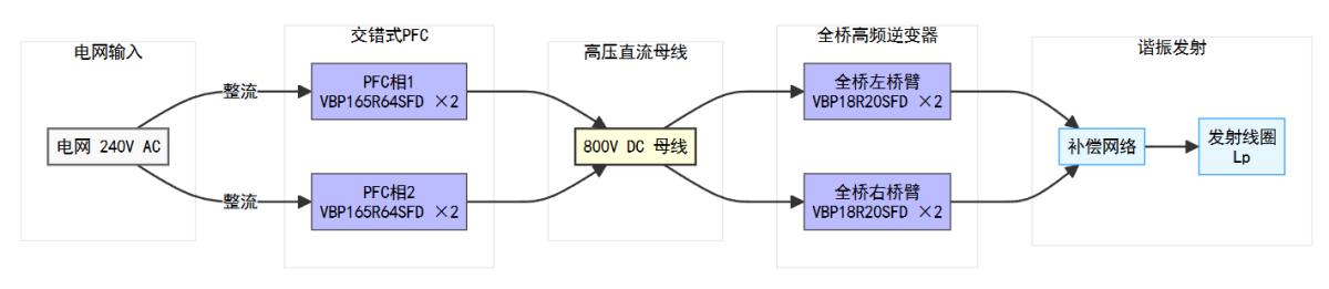
Ground charging base stations convert 240VAC three-phase grid power into high-frequency magnetic fields. Their high power and high voltage characteristics dictate that high-voltage superjunction (SJ) and SiC MOSFETs in TO-247 packages are the primary choices.

1. Interleaved PFC Rectifier Module
Function: Eliminates grid harmonics and outputs a highly stable 800V DC bus.
Core Component Selection: Must withstand 800V bus voltage and handle high current ripple of 11kW-22kW.
Recommended Model: VBP165R64SFD
Specifications: 650V/64A/36mΩ, TO-247, SJ_Multi-EPI technology.
Selection logic: Four of these devices are deployed in a two-phase interleaved parallel Boost PFC topology. Its ultra-low Rds(on) reduces the single-tube conduction loss at full load
of 11kW to an extremely low level, effectively reducing the burden on the base station liquid cooling system.
2. High-Frequency Full-Bridge Inverter Module
Function: Inverts high-voltage DC power into an 85kHz resonant current to drive the transmitting coil.
Key Pain Point: High-frequency hard switching easily leads to huge switching losses and turn-off voltage overshoot.
Recommended Solution: VBP18R20SFD High-Voltage Superjunction MOSFET
Specifications: 800V/20A/205mΩ, TO-247.
Design Highlights: Four MOSFETs are configured in the full-bridge topology. The 800V withstand voltage rating provides a 1:1 hard withstand voltage threshold for 800V bus systems,
perfectly matching the high voltage fluctuation suppression requirements of aerospace-grade systems compared to automotive solutions (400V bus with 650V MOSFETs). Its
SJ_Multi-EPI multi-epitaxial technology optimizes the reverse recovery characteristics of the body diode, significantly reducing the switching temperature rise at 85kHz,
making it an ideal choice for achieving soft switching (ZVS).
III. MOSFET Selection Scheme for Airborne Receiver
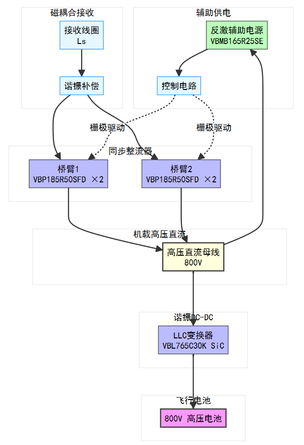
Airborne receivers face extremely stringent limitations in terms of size, weight, and heat dissipation, representing a technological high ground for eVTOL wireless charging.
Synchronous rectification and low thermal resistance packaging are the core selection criteria.
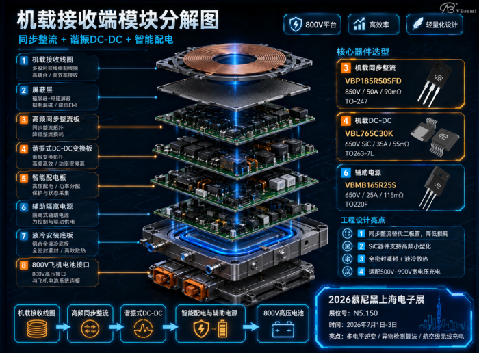
1. High-Frequency Synchronous Rectifier Module
Function: Efficiently converts the high-frequency AC power from the receiving coil into high-voltage DC power.
Technological Innovation: Traditional diode rectification must be abandoned in favor of active synchronous rectification technology to handle the high current and heat generation.
800V Platform Flagship Model: VBP185R50SFD
Specifications: 850V/50A/90mΩ, TO-247 package.
Rationale for Selection: For an 800V battery platform, the 850V withstand voltage provides a robust forward voltage margin. Four diodes are deployed in the full-bridge synchronous
rectification topology. Their extremely low on-resistance (SJ_Multi-EPI technology) reduces the rectified voltage drop from 0.7V (diode-level) to the millivolt level, directly determining
whether the overall efficiency can exceed 95%.
High Thermal Conductivity Layout: Utilizes a TO-247 long lead bending process, directly attaching to the onboard liquid cooling plate for double-sided heat dissipation.
2. Half-Bridge/Resonant DC-DC Converter
Function: Matches wide battery voltage range (500V-900V) charging.
Lightweight Core: To increase the switching frequency to over 200kHz and reduce transformer core weight, migration to a wider bandgap is recommended.
Recommended SiC Device: VBL765C30K
Specifications: 650V/35A/55mΩ (SiC MOSFET), TO263-7L.
Application Value: The extremely low gate charge (Qg) of SiC material enables high-frequency LLC resonant converters to achieve extremely high efficiency operation with no
reverse recovery loss, realizing "weight reduction" in airborne power supplies.
3. Intelligent Power Distribution and Auxiliary Power Supply
Function: Provides isolated power for flight management systems, heat pumps, and liveness detection (LFD) sensors.
Integrated Isolation Solution: VBMB165R25S
Specifications: 650V/25A/115mΩ, TO220F fully insulated package. Design advantages: For use in airborne flyback auxiliary power supplies. The TO220F fully insulated package eliminates
the need for ceramic gaskets, allowing direct mounting to the metal shielding housing. It provides highly reliable isolation between high-voltage ground and control ground, reducing
common-mode interference from foreign object detection (FOD) circuitry.

IV. Foreign Object/Live Object Detection (FOD/LFD) and Safety Interlocks
The eVTOL landing pad environment is complex, requiring real-time monitoring of minute metal or biological intrusions using highly sensitive coils.

High-Performance Analog Switch and Multiplexer: VBGQF1402
Specifications: 40V/100A/2.2mΩ (on-resistance), DFN8 (3×3).
Special Applications: Although this is a high-current device, its extremely low internal resistance of 2.2mΩ makes it suitable as a high-fidelity active switch in a detection
resonant circuit within a FOD system. The extremely low drain-source path resistance does not disrupt the high Q-value resonant characteristics of the coil, ensuring the
detection system has milliohm-level impedance change detection capability, making it perfectly suited for runway foreign object detection.
V. System Integration and Aeronautical Engineering Practices
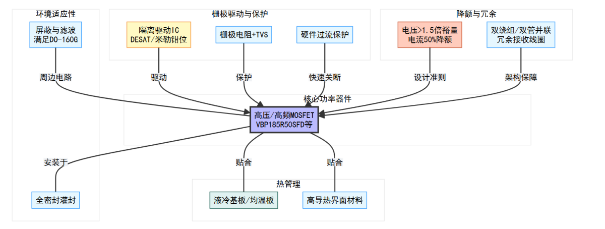
Thermal Management Synergy: The ground base station main switch (VBP165R64SFD) must have its case temperature kept below 90°C by a liquid cooling plate;
airborne SiC or superjunction large package devices must be coated with aerospace-grade thermal grease and used in conjunction with the
wing skin heat sink for heat dissipation.

Drive Architecture: All high-frequency MOSFETs must be paired with a high-voltage isolated gate driver IC (including DESAT/Miller clamp). A 22Ω resistor in series with the gate
is recommended to suppress oscillation, and a bidirectional TVS should be connected in parallel with the gate-source.
Derating Rigidity Requirements:
Voltage Derating: For 800V wiring harness systems, MOSFETs with a withstand voltage of 850V or higher (e.g., VBP185R50SFD) must be selected.
Current Derating: Continuous operating current is strictly limited to 40%-50% of the nominal current.
VI. Quick Reference Table for MOSFET Selection in eVTOL Wireless Charging Systems
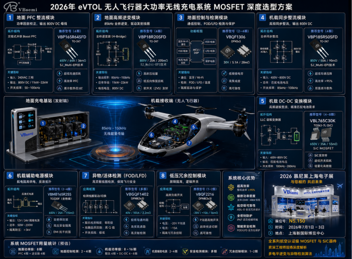
System Modules | Core Functions | Recommended Models | Package | Key Aerospace-Grade Adaptation Parameters |
Ground-based PFC | Power factor correction | VBP165R64SFD | TO-247 | 650V/64A, ultra-low 36mΩ on-resistance |
Ground-based inverter | 85kHz full-bridge high-frequency transmission | VBP18R20SFD | TO-247 | 800V high withstand voltage, handling resonant high voltage spikes |
Airborne rectifier | 800V synchronous rectification | VBP185R50SFD | TO-247 | 850V/50A, compatible with 800V flight battery platforms |
Airborne DC-DC converter | High-frequency resonant converter | VBL765C30K | TO263-7L | 650V SiC process, optimized for high frequency and low loss |
Auxiliary power supply | Avionics isolated power supply | VBMB165R25SE | TO220F | Fully insulated package, meeting high-voltage safety isolation requirements |
Safety monitoring | FOD coil drive | VBGQF1402 | DFN8(3X3) | 2.2mΩ extremely low on-resistance, lossless high-Q path |
Low-voltage redundancy control | Fault isolation/logic switching | VBQF2216 | DFN8(3X3) | -20V P-channel, facilitating direct high-side drive turn-off |

 Download now:VBP18R20SFD
*To request free samples, please complete and submit the following information.
Our team will review your application within 24 hours and arrange shipment upon approval. Thank you!
 中文
中文 English
 Back to previous page


