 中文
中文 English
TSM2301CX-RF-VB Product details
 Back to previous page
Product introduction:
**Application Introduction:** This device is suitable for low-power, small-signal switching applications, especially in the following modules: 1. **Power Switch:** - In low-power power switch modules, it is used to control the switch of the power supply. 2. **Power Management:** - Used in small power management modules to provide efficient power control. 3. **Signal Switch:** - Suitable for small signal switching circuits, such as audio amplifiers.
File download

Download PDF document
 Download now
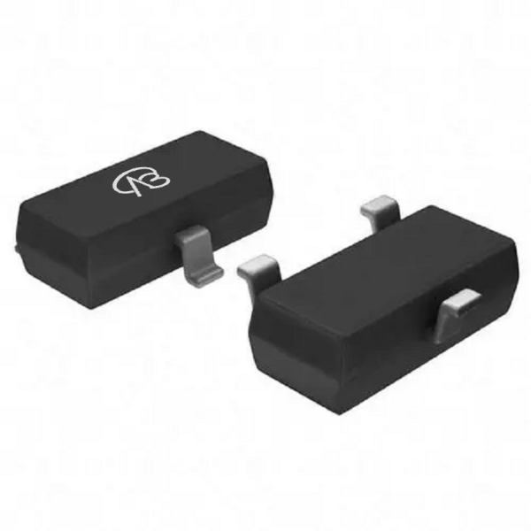
Product parameter:
| VB Package | Configuration | VDS(V) | VGS | Vthyp(V) | ID(A) | Rds2.5 | Rds4.5 | Rds10 | Technology |
|---|---|---|---|---|---|---|---|---|---|
| SOT23-3 | Single-P-Channel | -20V | -0.8V | -4A | 80(mΩ) | 65(mΩ) | 60(mΩ) | Trench |
| VB Package | Configuration | VCE | VGE | VGEth(V) | VCEsat15V | ICE | Technology |
|---|---|---|---|---|---|---|---|
| SOT23-3 | Single-P-Channel | Trench |
| VB Package | Configuration | VDS(V) | VGS | Vthyp(V) | ID(A) | Rds18 | Technology |
|---|---|---|---|---|---|---|---|
| SOT23-3 | Single-P-Channel | -20V | -0.8V | -4A | Trench |
| VB Package | Configuration | VDS(V) | VGS | Vthyp(V) | ID(A) | Rds6 | Technology |
|---|---|---|---|---|---|---|---|
| SOT23-3 | Single-P-Channel | -20V | -0.8V | -4A | Trench |
| VB Package | Polarity | Vz / VR | Pd | VF | IF | IR | Cd | Type |
|---|---|---|---|---|---|---|---|---|
| SOT23-3 | Single-P-Channel |
**VBsemi TSM2301CX-RF-VB** **Detailed parameter description:** - Type: P-Channel MOSFET - Rated voltage (VDS): -20V - Maximum current (ID): -4A - On-resistance (RDS(ON)): 80 (mΩ) @VGS=2.5V, 65 (mΩ) @VGS=4.5V, 60 (mΩ) @VGS=10V; VGS=12V - Threshold voltage (Vth): -0.81V - Package: SOT23-3
Domain and module applications:
**Application Areas:** - Portable Electronic Devices - Power Management Modules - Low Power Switching Circuits **Function:** - Provides efficient switching control of small signals - Realizes energy-saving control in low-power systems - For small signal switching applications **Precautions for Use:** 1. Please operate according to the recommended operating conditions in the data sheet. 2. Pay attention to the specific value of the threshold voltage and make sure to consider this parameter in the design. 3. Make sure that the current and voltage are within the specified range of the device to avoid damage to the device.
* Please note: the above is only an example application scenario, the specific application depends on the requirements and conditions of the system design. When using this device, consult its data sheet for detailed technical specifications and features
Technical support:
* If you have any questions about the product, please fill out the form to submit, we will reply you within 24 hours


