MOSFET Selection for High-Power & High-Voltage Applications: IPB120P04P4L03ATMA2, IPU80R4K5P7AKMA1 vs. China Alternatives VBL2403, VBFB18R02S
In today’s pursuit of high power density and robust performance, selecting the right MOSFET for demanding circuits is a critical engineering challenge. It goes beyond simple part substitution—it requires careful balancing of current capability, voltage rating, efficiency, thermal performance, and supply chain stability. This article takes two highly representative MOSFETs, the IPB120P04P4L03ATMA2 (P-channel) and the IPU80R4K5P7AKMA1 (N-channel), as benchmarks. We will deeply analyze their design cores and application scenarios, and then evaluate two domestic alternative solutions: VBL2403 and VBFB18R02S. By clarifying their parameter differences and performance orientations, we aim to provide a clear selection roadmap to help you find the most suitable power switching solution in the complex world of components.
Comparative Analysis: IPB120P04P4L03ATMA2 (P-channel) vs. VBL2403
Analysis of the Original Model (IPB120P04P4L03ATMA2) Core:
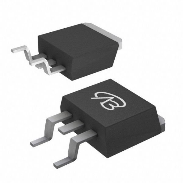
This is a 40V P-channel MOSFET from Infineon in a TO-263-3-2 (D²PAK) package. Its design core is to deliver extremely high current handling with minimal conduction loss in a robust power package. The key advantages are: an ultra-low on-resistance of 3.1mΩ at a 10V gate drive and a very high continuous drain current rating of 120A. This combination makes it ideal for high-current switching and power path control where efficiency and thermal performance are paramount.
Compatibility and Differences of the Domestic Alternative (VBL2403):
VBsemi's VBL2403 is also offered in a TO-263 package and serves as a pin-to-pin compatible alternative. The main differences lie in the electrical parameters: VBL2403 has a similar -40V voltage rating and an impressively low on-resistance of 3mΩ (@10V). Its continuous current rating is specified at -150A, which is higher than the original part's 120A, suggesting a potential margin in current-handling capability.
Key Application Areas:
Original Model IPB120P04P4L03ATMA2: Its ultra-low RDS(on) and high current rating make it perfectly suited for high-efficiency, high-current applications in 12V/24V/48V systems.
High-Current Load Switches & OR-ing Circuits: In servers, telecom rectifiers, and industrial power systems.
Battery Protection & Power Path Management: For high-capacity battery packs in energy storage or electric vehicles.
Motor Drives & Inverters: As a high-side switch in high-power brushless DC motor controllers.
Alternative Model VBL2403: With its comparable low RDS(on) and higher current rating, it is an excellent alternative for the same high-power P-channel applications, potentially offering lower conduction loss and increased current margin in upgraded designs.
Comparative Analysis: IPU80R4K5P7AKMA1 (N-channel) vs. VBFB18R02S
This comparison shifts focus to high-voltage switching. The design pursuit here is achieving optimal performance at 800V with a balance of switching loss and conduction loss.
Analysis of the Original Model (IPU80R4K5P7AKMA1) Core:
This 800V N-channel MOSFET from Infineon's CoolMOS P7 series, in a TO-251-3-21 (IPAK) package, represents advanced superjunction technology. Its core advantages are:
High-Voltage Performance: A 800V drain-source voltage rating suitable for off-line applications.
Optimized Technology: The CoolMOS P7 platform offers best-in-class figure-of-merit (FOM), combining low gate charge and good on-resistance (4.5Ω @10V for this 1.5A part) for high-frequency switching efficiency.
Robustness & Ease-of-Use: Designed with enhanced reliability and stability for demanding high-voltage environments.
Compatibility and Differences of the Domestic Alternative (VBFB18R02S):
VBsemi's VBFB18R02S is an 800V N-channel MOSFET in a TO-251 package. While electrically a functional alternative, key parameter differences exist:
It has a similar 800V voltage rating and a ±30V gate-source voltage.
Its on-resistance is 2600mΩ (2.6Ω @10V), which is significantly lower than the original's 4.5Ω.
The continuous current rating is 2A, slightly higher than the original's 1.5A.
Key Application Areas:
Original Model IPU80R4K5P7AKMA1: As part of the latest CoolMOS P7 family, it is ideal for high-efficiency, high-density power supplies requiring 800V breakdown.
SMPS (Switch-Mode Power Supplies): PFC (Power Factor Correction) stages, flyback, and LLC resonant converters for servers, adapters, and industrial power.
Lighting: High-performance LED drivers.
Solar Inverters: In low-power auxiliary or monitoring circuits.
Alternative Model VBFB18R02S: With its lower on-resistance and slightly higher current rating, it is well-suited for similar 800V applications where reduced conduction loss is beneficial, such as in auxiliary power supplies or specific low-to-medium power offline switching circuits.
Conclusion
In summary, this analysis reveals two distinct selection paths based on voltage and power levels:
For high-current, low-voltage P-channel applications, the original model IPB120P04P4L03ATMA2, with its 3.1mΩ RDS(on) and 120A current capability, is a benchmark for high-power switching. Its domestic alternative VBL2403 offers a compelling, performance-competitive option with similar RDS(on) and a higher 150A current rating, making it a strong candidate for direct replacement or new designs demanding maximum current handling.
For high-voltage N-channel switching applications, the original model IPU80R4K5P7AKMA1, leveraging Infineon's advanced CoolMOS P7 technology, provides optimized high-voltage performance and reliability. The domestic alternative VBFB18R02S presents a viable option with a notably lower on-resistance (2.6Ω vs. 4.5Ω) and a slightly higher current rating, which can be advantageous for improving efficiency in suitable 800V circuit segments.
The core conclusion is that selection is not about absolute superiority but precise requirement matching. In the context of supply chain diversification, domestic alternatives like VBL2403 and VBFB18R02S not only provide feasible backup options but also offer specific parameter advantages—such as higher current or lower RDS(on)—giving engineers greater flexibility and resilience in design trade-offs and cost control. Understanding the design philosophy and parameter implications of each device is essential to maximize its value in the circuit.


 Download now
 中文
中文 English
 Back to previous page


