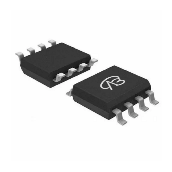
Product parameter:
| VB Package |
Configuration |
VDS(V) |
VGS |
Vthyp(V) |
ID(A) |
Rds2.5 |
Rds4.5 |
Rds10 |
Technology |
| SOP8 |
Single-P |
-30V |
|
-2.5V |
-13.5A |
|
15(mΩ) |
11(mΩ) |
Trench |
| VB Package |
Configuration |
VCE |
VGE |
VGEth(V) |
VCEsat15V |
ICE |
Technology |
| SOP8 |
Single-P |
|
|
|
|
|
Trench |
| VB Package |
Configuration |
VDS(V) |
VGS |
Vthyp(V) |
ID(A) |
Rds18 |
Technology |
| SOP8 |
Single-P |
-30V |
|
-2.5V |
-13.5A |
|
Trench |
| VB Package |
Configuration |
VDS(V) |
VGS |
Vthyp(V) |
ID(A) |
Rds6 |
Technology |
| SOP8 |
Single-P |
-30V |
|
-2.5V |
-13.5A |
|
Trench |
| VB Package |
Polarity |
Vz / VR |
Pd |
VF |
IF |
IR |
Cd |
Type |
| SOP8 |
Single-P |
|
|
|
|
|
|
|
Model: IRF9310TRPBF&9-VB
Silkscreen: VBA2309
Brand: VBsemi
### Detailed parameter description:
- **Package type:** SOP8
- **Channel type:** P-Channel
- **Rated voltage (VDS):** -30V
- **Maximum continuous current (ID):** -11A
- **On-resistance (RDS(ON)):**
- @ VGS = 10V: 11mΩ
- @ VGS = ±20V: No specific value provided
- **Threshold voltage (Vth):** -1.5V
Domain and module applications:
### Applicable fields and modules:
1. **Load switch module:** Due to its negative power supply voltage and moderate current capability, IRF9310TRPBF&9-VB can be used to design load switch modules, such as switching power supplies for loads.
2. **Power switch:** In some power switch applications that require P-Channel MOSFET, such as power switches and inverters.
3. **Power inverter:** Suitable for power inverter modules that require negative power supply voltage to convert DC power to AC power.
### Precautions for use:
1. **Voltage level:** During use, make sure not to exceed the rated voltage of -30V.
2. **Current limit:** Do not exceed the specified maximum continuous current, which is -11A.
3. **Threshold voltage:** Note that the threshold voltage is -1.5V, and the appropriate voltage range needs to be considered when designing the circuit.
4. **Heat dissipation:** For high load applications, adequate heat dissipation needs to be provided to ensure that the transistor operates within a safe temperature range.
5. **Static electrostatic protection:** During operation, take appropriate electrostatic protection measures to prevent damage to the transistor.
* Please note: the above is only an example application scenario, the specific application depends on the requirements and conditions of the system design. When using this device, consult its data sheet for detailed technical specifications and features
Technical support:
* If you have any questions about the product, please fill out the form to submit, we will reply you within 24 hours


 Download now

 中文
中文 English
 Back to previous page