Product parameter:
| VB Package |
Configuration |
VDS(V) |
VGS |
Vthyp(V) |
ID(A) |
Rds2.5 |
Rds4.5 |
Rds10 |
Technology |
| SOT23-3 |
Single-N |
60V |
±20V |
1.7V |
0.3A |
|
3100(mΩ) |
2800(mΩ) |
Trench |
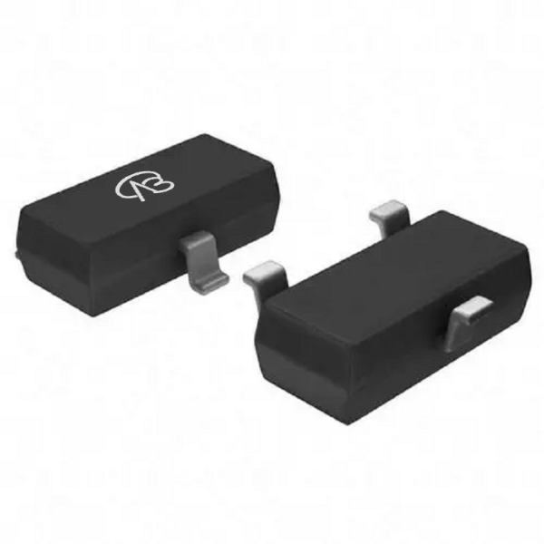
Model: 2SK1590-VB
Silkscreen: VB162K
Brand: VBsemi
Parameters: N-channel, 60V, 0.3A, RDS(ON) 2800mΩ @ 10V, 3000mΩ @ 4.5V, ±20Vgs (±V); 1.6Vth (V)
Package: SOT23-3
Detailed parameter description:
1. Channel type: N-channel
- This means that this is an N-channel MOSFET, which is commonly used in electronic devices, especially applications that need to control positive voltage power supplies.
2. Rated voltage (VDS): 60V
- This is the maximum voltage that the channel MOSFET can withstand, indicating that it is suitable for circuits that need to handle voltages up to 60V.
3. Rated Current (ID): 0.3A
- This is the rated current of the trench MOSFET and indicates the maximum current load it can handle, although it is relatively low.
4. Static Drain-Source Resistance (RDS(ON)):
- RDS(ON) is the resistance of the trench MOSFET in the on state. At 10V, its resistance is 2800mΩ, while at 4.5V it is 3000mΩ. This indicates that its resistance is relatively high in the on state, but it can be used in low power applications.
5. Gate-Source Voltage Rating (Vgs): ±20V (±V)
- This indicates that the gate-source voltage is rated to range between plus and minus ±20V. The gate-source voltage is used to control the on and off states of the MOSFET.
6. Threshold Voltage (Vth): 1.6V
- This is the threshold voltage of the trench MOSFET, indicating the voltage that needs to be applied to the gate for the device to start conducting.
Domain and module applications:
For example:
1. Signal switch: This MOSFET can be used to control the switch of the signal line to achieve signal switching and amplification.
2. Low-power amplifier: In some small audio amplifiers and amplifier circuits, it can be used for signal amplification.
3. Low-power power management: Suitable for power management and switching of low-power devices.
4. Logic level conversion: used for logic level conversion and logic gate implementation.
* Please note: the above is only an example application scenario, the specific application depends on the requirements and conditions of the system design. When using this device, consult its data sheet for detailed technical specifications and features
Technical support:
* If you have any questions about the product, please fill out the form to submit, we will reply you within 24 hours


 Download now

 中文
中文 English
 Back to previous page