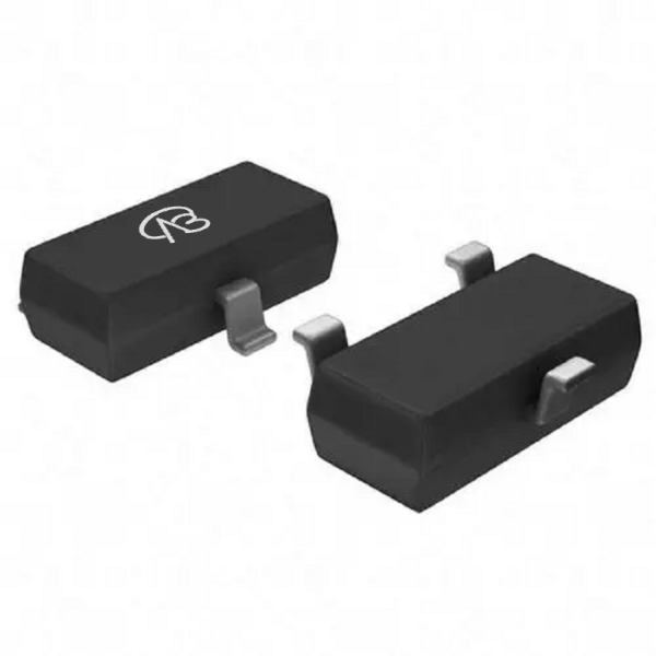
Application introduction: SSM3J01F-VB is a P-Channel channel power field effect transistor (Power MOSFET) packaged in SOT23-3. This device is widely used in power switching, power management, and other applications requiring P-type channel.
model: SSM3J01F-VBSilk screen: VB2355brand: VBsemiparameter: -Package: SOT23-3 -Channel type: P—Channel -Maximum withstand voltage: -30V-Maximum current: -5.6A-On resistance: RDS(ON)=47mΩ @ VGS=10V, VGS=20V -Threshold voltage: Vth=-1VDetailed parameter description: 1. **Channel type:**P—Channel, suitable for needsPType-channel power switch and management circuit design. 2. **Maximum withstand voltage:** -30V, suitable for low and medium voltage circuits. 3. **Maximum current:** -5.6A, supports relatively high current demands. 4. **On resistance:** RDS(ON)=47mΩ @ VGS=10V, VGS=20V, low on-resistance, helping to reduce power loss. 5. **Threshold voltage:**Vth=-1V, defines the turn-on threshold of the device and affects its conduction state in the circuit.
Domain and module applications:
Main application areas: SSM3J01F-VBCommonly used modules in the following fields: 1. **Power switch module: **It is suitable for power switching circuits to realize power switching control. 2. **Power management module: **Can be used in power management circuits to regulate current and voltage. 3. **Driver module: **Used in driver circuits as current or voltage switching elements. effect:In the above module,SSM3J01F-VBIts functions mainly include: - **Power switch module: **Control the power switch to disconnect and connect the circuit. - **Power management module: **Used in power management circuits to regulate current and voltage. - **Driver module: **As a switching element, it is used in driver circuits to achieve switching operations. Precautions for use: 1. When designing the circuit, ensure that the operating voltage and current do not exceed the maximum withstand voltage and maximum current of the device. 2. Pay attention to the range of threshold voltage to ensure that the device can operate normally within the required voltage range. 3. Carefully read the manufacturer's data sheet for more details on use and operation to ensure proper application.
* Please note: the above is only an example application scenario, the specific application depends on the requirements and conditions of the system design. When using this device, consult its data sheet for detailed technical specifications and features
Technical support:
* If you have any questions about the product, please fill out the form to submit, we will reply you within 24 hours
*To request free samples, please complete and submit the following information. Our team will review your application within 24 hours and arrange shipment upon approval. Thank you!
X
SN Check
***Serial Number Lookup Prompt**
1. Enter the complete serial number, including all letters and numbers.
2. Click Submit to proceed with verification.
The system will verify the validity of the serial number and its corresponding product information to help you confirm its authenticity.
If you notice any inconsistencies or have any questions, please immediately contact our customer service team. You can also call 400-655-8788 for manual verification to ensure that the product you purchased is authentic.


 Download now

 中文
中文 English
 Back to previous page